I needed a 10-20watt power amp, with a very good sound. As far as I could think, I needed a triode single ended amp; but in order to get such a power out of a SE amp requires either best-of-breed 300Bs, or high voltage tubes like 211 or 845.
Any solution requires very high cost design (a single WE 300B is sold here in Italy at about 600US$, and for the high voltage tubes special, difficult to find, components, or series of not so common components are required); what's worse, the whole result depends a lot on the transformer, which is anyway very expensive, but no one can really be sure of the sound of a transformer in his own design.
With high voltage tubes one must also take into account the risk working with lethal voltages... while with 200V the risk is normally limited to a very unpleasant and strong shock, and only by direct contact with anodic voltage conductors, with 1000-1200V the risk is immediate electrocution even without any direct contact (an electric arc can set up....)
So if you want hard and pure SE design with more than 10W output power, you have to spend a lot of money for no sure result... and no sure result possibly even with regards with your remaining lifetime....
So the only wise solution seems to be to look for something less expensive: a parallel single ended amp can be a good start; the tubes could be either 2A3 or even tetrodes or penthodes in triode configuration (even though these last would allow other configurations, ultralinear or penthode, normally the triode one is according to me preferable: all my amps, born as ultralinear or penthode design, are currently in triode mode, even though this reduces drastically the available output power).
The issue, again, is the output transformer, which presents the same problem as above.
So in the end I was gathering information about good output transformers for a medium power PSE amp, probably with EL34 tubes, which would give about 12W output power.
But one day a friend comes out with a review of a really good sounding power amp, designed for several different configurations, further more configurations available with simple modifications, and with, as far as it is possible to understand, very good output transformers. It is the last son of an ancient (?!) and very well established family, known in the whole realm for their beautiful voices.
One possible configuration is PSE and tubes are EL34...
How could you stop listening to that little naughty and noisy voice that is telling you "hey, that's your amp... why spend lot of time and money to design it? It is there, ready to go, perhaps better than you will ever be able to do... that's your amp, listen to me... at least, you could use it as a reference amp... And it is less expensive that the couple of transformers you were thinking about... and Thorsten has tested it, and says it's good, very good: no risk, that's your amp..." (don'y you hear that kind of Voices? I'm so sorry for you, as my own Voice is rather accurate and precise in her own indications and is really comfortable to have her own full support in spending a lot of money; there only a few problems with Her; first problem is that my own Voice does not earn a wage, which is unpleasant, but even worse is that as a consequence she seems far superior to any economical problem; second problem is that I cannot share my Voice with my wife... I asked the Voice, but seems it is definitely not possible... She just have her own personal Voice, with a far different - and alas not cheap - specialization, and as it seems it is not at all easy to replace it...).
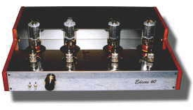
Well all this just to explain how it was that an Edison 60 kit happened to knock at my door...
Before going to the notes, anyway, I think it is important to make it clear that this is definitely no beginner kit. It takes a rather long time to complete it (more than spare time in a weekend, anyway), a few solutions are not so clear, a few more holes must be drilled; not all of the configurations are covered neither by the manual nor by the supplied schema, so if you do not have a clear idea of the electrical schema the system should have you could find yourself in big trouble. And the results? Wait son, wait... there are so many things to say...
The kit arrived in a very sturdy 12kg box. The packaging is very professional, and as heavy... as Thorsten stated. I ordered from the beginning the extra power transformer, the high quality input and output connectors (only two input connectors: I needed a power amp...) but no cosmetics.
I did not ordered the extra power supply smoothing capacitors, as the cost was, according to me, a little excessive. I was able to buy higher voltage capacitors and the other components for a lower amount. Obviously, quality could be a valid explanation of the difference; but the difference seems really rather high. I would suggest anyway to order the extra power supply unit, as here part of the cost is possibly justified by the PCB.
The sheet metal cabinet has a good quality level, has several threaded inserts and is painted with a good covering matt black paint. An overall quality structure.
There is only one strange problem: there are several iron coloured screws to be mounted on the front part, which can hardly be explained, as a few black screws are anyway inserted in the kit; probably they match the polished steel top. By the way, those black screws seems not so easy to find (unless you look into RS part list...).
On the specification list there is one wrong piece of information. It is perhaps one of little account, for most of you, and to some extent it really is, but on another point of view it is extremely disappointing, because it is really a parameter very easy to measure (anyone of you can surely do that...) and can cause an unexpected expense (not even so low... probably more than half the cost of the amp!!!) to be necessary for proper installation of the amp.
The point is just the overall dimensions: the height (reported as 11.5cm) is wrong, or, better, it is just the height of the cabinet without the protruding tubes; the overall dimension is around 17cm, so that it can really be not possible to accommodate the amp in any standard rack, apart from the top, which anyway should better be occupied by a turntable; actually standard racks normally have 16cm between floor and ceiling.
By the way, only a few rack series can accommodate amps this high, taking into account that the tubes get really hot (but also the amp cabinet is not as cold as I would like) when the amp is switched on even in wintertime and therefore adequate free air must be available above the amp, both to prevent excessive tube heating and to avoid burning what's placed above; this can in turn possibly oblige you to choose an expensive rack.
The best solution is probably to leave it on the floor, but take into account how much uncomfortable it is to work on the floor, and a kit (at least my kits...) takes little time to get born, but a long long time to grow up to their final shape...
Input and output connectors are another issue. The standard ones are again really disappointing. The output ones are probably CE compliant, but are just very low cost plastic banana sockets with a simple single contact inside. No gold. No chance of using neither naked wire nor forks.
They happen to be the worst output connectors I ever found in a kit. I would never take into account any hypothesis of using them, especially in a 900$ design (but probably this is my fault: I suspect they work perfectly, and hence anything more expensive is not really necessary...). The standard input connectors are plain RCA sockets, mounted in couples on little rectangular insulating material bases. No gold either.
The high quality connectors are a whole different concept (and quality). The output ones are Audion, gold plated, sturdy and shining connectors, with a large knob to allow an easy tightening; they accept bare wire (not so huge diameters, I found a few problems inserting a Supra 4 in the holes...), banana plugs and forks.
The input connectors, again from Audion, are high quality, single piece, Teflon(?) insulated, gold plated sockets. The holes in the chassis accept promptly, without even the slightest trouble, the special connectors (I must admit I did not even test the standard ones. As a matter of fact, the banana sockets result presently missing in action... I cannot drive myself to think their lost to be any damage...).
The costs of the special connectors is not low, but not even extravagant. Input connectors cost more than the apparently identical connectors I am able to find here in Italy, but a better plating could perhaps justify the difference; output connectors have a cost which is a bit lower that the ones I normally use, seem to be of slightly higher quality, more massive and better insulated but the ones I use accept thicker wire and have a far more sparkling look.... For sure neither is CE norms compliant...
By the way, when you order the high quality connectors, you pay for both series, the standard one and the high quality one, which seems a little of a waste: it's true that the standard components are really low cost, and that the cost of taking them out of the kit could be far higher than their cost, but no one wants to pay for something he is not interested in (it is probably more a fact of image then anything else, anyway: the total cost of standard connectors is possibly less than 10$).
Wiring is another point where you can make things better with little expense. The solid core wire supplied is acceptable, but the other wiring is not so exciting. Especially the signal wiring seems to be not so high quality. Instead of the shielded wire listed in the instructions and parts list I found only a 7 pole flat cable (or better a 7 pole stripe of a multiconductor flat cable: it appears to have been longitudinally cut off a wider cable), supposedly to be used to convey the three inputs from the input socket to the input selectors.
In a power amp the problem could be really not so important. The fact is that Edison 60 is an integrated amp with a rather high voltage gain (input sensitivity is 250mV for full output in push pull mode; I have not measured nor computed it in PSE mode, but gain is similar; by the way I modified the gain by not inserting input stage cathode bypass capacitors and by eliminating any feedback).
This means that the input signal is expected to be quite low, and hence possibly subject to be disturbed by PSU units and lines.
The original idea of using shielded wire seemed to be correct, even though an high quality wire should be used. As an alternate solution you should better use a twisted couple of solid core wires, one for signal and the other for ground, for each input.
The real problem, anyway, is not the wire type, but its length. To tell the truth, I do not like the whole input selection arrangement. There are quite a few problems, according to me.
First, the input connectors are far away (40 cm+) from the input selectors. This obviously, combined with the connection quality, raises the risk of picking up disturbs. What you can nowadays find in any medium or high quality preamplifier is that the input selector is placed as near as possible to the input connectors; when these are on the back panel, there is a extension bar that connects the selection knob on the front panel to input selection device, if this is of mechanical type.
This is not possible in the Edison 60 arrangement, as an output transformer is placed between input connectors and front panel. Probably the best solution would be to let the signal in trough the left side panel.
The input selector is another not so brilliant solution: two separate two position switches have been used in a series arrangement in order to be able to select three inputs. This means that signal must go through at least two contacts before reaching the first stage input.
I am able to find a rotating, gold plated selector, with apparently sealed plastic housing that probably cost not so much more than the two switches, if they are really of similar good quality. Obviously this would require one more knob, but the one supplied is a very high quality, solid aluminium one, that it would have been not difficult to find two lower quality knobs for the price of one... and the look would have been far better than with the two front switches...
Standard volume potentiometer is a low cost carbon one; same type I used in my MW Pre 01, as it seems. Well, it is not an high quality piece, but it works and even rather well. I wound up mine in Teflon mummy tape, in order to seal it perfectly; in my pre there is not yet any problem or clicking noise after about six months (note that these have been prototype-life, hard duty months... with wooden powder and similar things around...).
The sound seems better than high cost film potentiometer's one, but the expected lifetime should definitely be not comparable. The cost too is less than one tenth, anyway...
The remaining components are normal, industry standard components, with no special components to enlighten the set.
The schema could be easily criticised, if you analyse it as a PSE schema. Actually it is immediately clear that one of the driver triodes is completely unused, while could have better been used to set up a driver stage with higher current capability.
Anyway, this amp was born as a push pull amplifier, and the PSE version is only a possible alternate configuration made available to the builder. From this point of view the schema seems absolutely adequate and correctly implemented, and the extra configurations available a beautiful gift to be greatly appreciated.
There are anyway a couple of things more that made me rather uncomfortable.
The first one extends to a good deal of components: there are several components used so that their static power dissipation is nearly up to the rated maximum value. This is a correct design procedure when you are designing low cost products which cannot cause any harm even though some components can get very hot, as they are assumed to work always in a closed structure, and are supposed not to be modified to any extent. In a kit, and especially a high level kit as this, such money sparing practices are less acceptable.
As a matter of fact, a few resistors get really very hot, more than I like any components to get when I am expected to work on the naked circuit board.
In my projects I normally select components with a rated power 2 or 3 times higher than the estimated power dissipation: this allows for a low temperature and fully safe operation, even during first tests, where a wrong connection or a roughly approximated calculation can cause unexpected power dissipation to occur. By the way, the kit doesn't not present itself as a "all included, one way" kit for beginners, but as a complex and advanced kit for people who can make a few choices by themselves; hence the designer could have taken into account the fact that a few changes could possibly be made to the original circuitry... but it's also true that anyone daring making any change to such a complex design must have solid electronic design knowledge.
Anyway, if you are going to make any change in the circuit, you'll better check power dissipation in the various components, as it is well possible that changes cause the rated power of any component to be overrun.
The second point is not a major one, but not so secondary, in the end, and is referred to the anodic voltage power supply capacitors. The power supply is solid state (this is not at all to be considered a bad word and not even a defect: a solid state power supply normally gives a much faster behaviour and better bass control, often with deeper bass) and is followed by a single (in push pull configuration) or double (in single ended with extra components) pi resistive filter with capacitive input.
All this is definitely standard. The first problem is that all filter capacitors are 110uF, which is really a low value, taken into account the 140mA current running in each board: the output ripple cannot be too low. The second problem is that these 110uF 500V components are obtained as series of two 220uF 250V components, correctly in parallel with a resistive dividing network to ensure the HT voltage to part equally on the two capacitors; this obviously causes anyway an higher capacitor's internal resistance to appear.
The third problem is that the expected voltage across these capacitors is 460V, but there is some risk for the rated voltage to be overrun because of a mains voltage higher than standard, with possible destruction of the capacitors...
I would have far preferred single 600V capacitors everywhere, but the cost would have been probably far higher; moreover, while you can find electrolytic capacitors rated up to 450V easily enough, it is far more difficult to find 600V capacitors.
The manual is, according to me, rather well written, even though it covers only the most standard configurations. If you choose to double the PSU, or to install the extra smoothing capacitors, then you'll discover that the manual does not cover at all this case, which is somewhat unexpected and maybe disappointing for someone, even though you have read through it once before buying it.
There is some problem in the numbering of external connection points on the schema with respect with the numbers shown on the manual and on the PCB; they seem slightly mixed up, but as far as you follow PCB silk print and manual no problem arise.
In the following I give some more instruction for dual mono PSU configuration: note that the description apply ONLY TO THIS CONFIGURATION: refer to the manual for any other configuration.
The extra smoothing components can be mounted on the standard main board just following the position assigned in the layout; they are C20,C21,R50,R51,R52.
For the dual mono configuration, you should better try to mount the PSU boards as far as possible from the output transformers. First of all, you must drill two holes in the bottom panel in order to be able to assemble the power supply transformers one aside the other between the two output transformers. Then you must find a place for PSUs. The normal position is a central one, but only one PSU unit can take place there.
I used for the right PSU a set of matching holes exactly in front of the PSU right transformer but I drilled some more holes in similar position for the left PSU board.
Looking carefully and using the left (each hole in the PCB is doubled) PSU board holes for the right PCB to mount the pillars and vice versa for the other one you could possibly find at least some matching holes even for the right board.
Another thing that changes is obviously the power supply and ground lines arrangement. Have a careful and complete look at the manual, and rearrange anything according to the double PSU before starting any connection. One little problem consist in the identification of wires coming out of the transformer; colours are not so different as to be immediately recognisable, so that at least a tester is required to couple them correctly. Both transformers must really be mounted with the wire coming out towards the front of the amp, not only to avoid disturbing but mainly to avoid having to solder on short length of wire to be able to complete the connections....
Be especially careful with the filament supply:
In order to avoid mains noise to be picked up by the circuits, the filament supply wires should be strictly twisted up.
There are plenty of wires coming from the cabinet or EL34 tubes to the PCB, so that to take one PCB out later is not impossible, but surely hard work. Filament connections to EL34, anyway, could be made permanent simply by soldering them before installing the PCB, and letting them pass between the PCB and the cabinet wall; there is anyway a little risk of overheating and also that the wire go along at a too short distance from audio circuits, so the solution is not so safe and should be checked carefully. I did not implement it.
One last hint: check carefully the soldering of 6922 sockets: soldering them is not simple (the hole has such a diameter that the solder can take place only at the sides of the pin, where it is most thin), it is also difficult to see if the joint is good, and I suspect that mechanical stress due to tube insertion can also break the soldered joint.
If you find problems, you can try to solder it without dismounting the PCB by heating with the soldering iron the pin of the tube socket on the internal side of the pin and inserting in the PCB hole on the external side of the pin the tin wire, so that it melts down at the connection between the PCB and the pin. This is a an absolutely not correct practice, which I only tell you as I found that works... and can spare you about one hour work. Be very careful not to overheat neither the PCB nor the pin.
No other change has been implemented, as far as I can remember (up to now....).
Let's then write about listening tests. Listening tests? Well, indeed, not really listening tests... no, I would not call them that way. Yes, well, I could even call them that way, but not in the common way... they were not really tests... It was not possible...
The problem here is far bigger than above. That is, when I first switched on the Edison 60 connected to my Linn Mimik through the MW Pre 01 and driving Snell K III, just for the first functional test, without any kind of burning in, I expected a rather rough, uneducated sound, excessively brilliant as often happens with Sovtek brand new tubes.
I really did not expect so much from the amp, after all little things that made me uncomfortable I had found while assembling it, was nearly sorry of having built it.
Well, after about ten minutes I had radically changed my mind. As Thorsten said, I too had never heard sounding that way in my system.
First thing, the -2dB @ 70Hz Snell were finally able to show that they could release some bass even with a single ended tube amp. Clean, stable, full bass, with a good control, even though not obviously going down to the deepest bass. But you cannot expect this to happen with the Snell K III.
The medium frequencies were really nice, full, complete. Really good.
Then the treble, clear, not at all thin, transparent, perfectly balanced with other bands, just a little edgy (this disappeared completely after a couple of weeks of continuous burning in).
The image was large, perhaps not so deep, a little projected towards the listener, but never overwhelming him, that is never rising to an enormous size like sometimes happen.
Absolutely more stable than with any other amp I have used in the past, and I would say as stable as the best (sound reproduction...) performances I could ever listen to. I could really listen the image to rise higher than the loudspeakers, which is not so easy: my 'speakers are placed a little (euphemistic...) lower than they should (that was the first thing Lucio said when he had to listen to my system...), but the stage was about 20 cm higher than the 'speakers, so that a rather correct sized image of singers could be obtained.
I got through the Ultimate Demonstration Disc by Chesky. After a while my wife came in and said: "But the singer (Rebecca Pidgeon, by the way) seems to be here in the room!!!".
In one word, you listen to Music itself. Or better you should to: the soundstage is so correct, proper and detailed that you find it difficult to put your attention into the Music; you really follow each player and his own music line; you can really listen to the Musicians making Music.
The sound, by the way, grew even better after burn in, even though not as much as I would expect (it was already too good just from the beginning...).
Well, is there any problem then? Yes, but really minor ones.
I had some mains noise coming out of speakers (sensitivity 90dB at 1W / 1m); I found this noise's level decreasing since first time I switched the amp on; perhaps it is due to electrolytic capacitors burn in. Anyway shielded wire between the input connectors and the volume potentiometer and an aluminium foil around all the not connected wires coming out of input transformers helped reducing its high frequency components a lot.
Even decreasing the amp gain with its volume potentiometer helped. Currently, with no other change, the noise is not audible for any practical purpose. Take into account, anyway, that my preamplifier has an extraordinarily high output impedance, which for sure make it possible for some noise to be picked up in the interconnection; possibly, with other pre there would not be any problem.
Another thing are the coupling capacitors (I used the standard ones). As far as I can judge from the sound of the complete amp, they tend to colour the sound a little. Probably good paper and film capacitors could be better, but I would like to be sure that the sound does not change too much.
There also is the little cost problem: if you buy Jensen capacitors you would spend something like one sixth of the complete amplifier (you need 8 capacitors)... A little too much? Don't know, I'm trying to gather the amount to buy them just to check...
Last thing: I just made short tests comparing Edison 60 sound when directly connected to the CD player and when connected through my MW Pre 01 pre-amp. It seems that a good pre-amp can help a lot. It is not at all surprising, even though it doesn't sound so correct with an integrated amp.
I don't think it is necessary to explain if it is worth buying it, and to what extent. I just must say that the above notes about the cost of a few details are simply ridiculous, compared with the sound quality level. And I must add that since I first switched it on I never came back to listen to the old power amp...
Only one last note for the builder and the manufacturer: I cannot imagine how it could play if all the problems noted above were completely solved. Perhaps they are not even real problems: the Edison 60 sound is such that after listening to it one is not so sure that all the special cares used by DIY cranks in building their amps are of any use if compared with an outstanding design and a good output transformer with a standard level implementation.
Well, this is all. Listening tests? Sorry, I have no time for such stupid things. I have a lot of brand new CDs and a few LP too to listen, and I must play again all my old records of any type, as through the Edison 60 they all seem to be new stuff: even a DG Brahms record I always despised, now sounds rather good...
So I'm really sorry, but please do not bother sending me any mail for the next couple of seasons, as I think I will really be too busy listening to the Music to answer you...
© Copyright 1999 Giorgio Pozzoli
How to print this article