![[The TNT Convertus]](../gif/convertus.gif)
![[The TNT Convertus]](../gif/convertus.gif)
The Convertus DAC was presented on this pages a couple of years ago. It has clearly been a success, given the number of interested DIYers that have got in touch with us.
Nevertheless, I have always been conscious of at least one major technical limitation, that by the truth was hidden enough in listening to prevent most of people from grew conscious of it, but at the same time evident enough for me to usually recognize Convertus during blind comparison tests.
The signal coming out of a zero oversampling DAC is "stairways" shaped, with a step after each conversion. In facts there is no filter inside the DAC, and the external output filter is very mild. So the output signal stays at the same level between one sample and the next, and then moves fast to the next level and stays there until the following sample comes. This is a desired effect, obtained by storing the last sample inside the chip and using it to pilot the D/A converter, and "holding" it in place until a new complete sample is available.
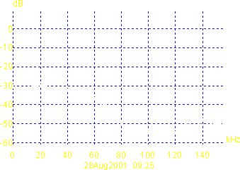
This anyway causes a very heavy modification in the frequency response. This is called sinx/x filtering, and causes a null output level at Fc and all higher level multiples of Fc.
As you see its effect is already visible at 20Khz and consist in a frequency response drop of a few dBs.
Hum... I know that some of you will say I am a fool. Some of you have built special filters to simulate the effect with standard CD players, and I am afraid there is at least a couple of industrial companies doing the same. But from the technical point of view it is a problem, and I consider it as such.
The search for a solution started even before the first article was published. I was looking for a solution that granted a flatter frequency response module and no alteration of its phase and not too complex to implement. Given the opposite requirements, I did not really expect to find a solution. But some study of the problem allowed me te figure one out, even though this meant to take the Kusunoki assumption to the limit (and further...).
I just want to be very clear. The proposed solution is such that applying it in some cases can be much worse that the problem. It can also be dangerous for your loudspeakers. But I tested it with four different chains, including both solid state and tube pre-amps and amps, and had some other friends (thanks, Ruggero) to test it and it caused no problems to anyone. In my system I always use the new version, but there still is a risk that someone of you might find problems. Please LOOK AT OUR GENERAL DISCLAIMER.
On the other side the cost of the modification is really low (less than 20 USD, I would say) and moreover there is a switch that enables the user to eliminate its effect, so that you can test it without any major expense and decide by yourself if it is the case of using it or not.
The idea is really simple. The filtering effect caused by sample-and-hold circuits depends not really on the sampling period, but on the holding period (that is the time the signal remains constant for): the lower the holding period, the higher the (first) cutoff frequency. Taking this at the limit, you reach the null holding period, which is the situation for which theory accounts for, and in which there is no drop at Fc/2.
In practice you cannot reach this point: theory is based on the pulse signal that is a signal with unit energy and null duration, which is not possible to implement in practice. But we can approximate this situation by reducing the duration of the holding period to a fraction of the sampling period, which is exactly what happens in case of decimation (see TNT-Convertus part 1).
A decimated signal hence has a (far) better frequency response at Fc/2 if compared with a non decimated signal.
Just to have an idea of what is going on in the time domain, look below: the following are the 'scope view while reproducing a 1KHz test tone (top), spectrum analysis for the same situation (center) and spectrum analysis while reproducing white noise (bottom) of the output of Convertus (left) and Convertus Decima (right). For the sake of semplicity, the decimation factor in Convertus Decima has been set to 2. The bush around the main lines in the center right picture are mainly "fake" signals, aliases created by the measuring instrumentation due to its limited sampling frequency.
Is there any tradeoff? Yes, and some heavy one.
First of all, the decimated signal contains a very heavy alias component around Fc. This component is an image of the audio signal, and its level is only a few dB lower than the audio signal level (!!!), and far higher in level than in normal Convertus. This alias signal is not audible or at least hopefully cannot be consciously interpreted as music by our brain (at least this is the Kusunoki assumption that an antialias filter is not required because of the limited range of human hearing.... not everyone agrees about it), as it is 44.1KHz, but can potentially cause any kind of problem in the other system components. In most components it could probably only increase dramatically distortion, but it could also destroy the tweeters, if it reaches them, as it contains an energy nearly equal to the full signal energy, while the tweeters are normally dimensioned for a small part of it. So be very careful and check what is going on in the rest of your system, if you are using Convertus Decima.
Second, the energy of the audio signal decreases drastically: you loose as much as 6dB in theory, but in practice it seems a much heavier effect. In case the sensitivity of your chain is low, you could find difficult to reach the normal sound level (note anyway that this in turn protects the tweeters).
Third, the fact that the audio frequency power is reduced invites you to turn the volume knob to the right. But the peak signal value is absolutely the same, so the amplifier risk to saturate, making the first problem even worse.
The correct approach to implement decimation consists in modifying the flow of signals from the receiver to the DAC: this allows to use digital signal processing techniques without any polluting effect on the analog signal.
Unfortunately this approach is rather complex to implement: the DAC in facts must work at n*Fc, while the input stream is a Fc, so that a "clock speed rate" change is necessary. This in turn requires a complex arrangement including a serial-in/parallel-out 16 bit register loaded with a 44.1KHz clock, whose content is periodically transferred to a parallel-in serial-out register from which the signal is clocked out at an higher frequency.
I have a digital design ready, but I have not implemented it and obviously not tested, so I will not present it now. And I am not sure I'll ever do...
There is another possible solution, anyway, that even though does not grant the same unpolluted output of the correct one, allows to reach the same result with a far more limited effort. This can be obtained by processing the output signal after the DAC chip. Yes, I know it sounds crazy... It took me almost one year to make it work, but now it works really fine!!!
In this case the output signal must be obtained by switching between the normal DAC output and a level corresponding to the average value of the DAC output.
This can be achieved using 4 bilateral switches 4066 (the HCT high speed version has been choosen). The switches can be seen as relais. Two switches are used for each channel, one is closed when the other one is open and vice versa as the control signals are one the negation of the other. The 1543 output is connected to the input of one switch, while the average value, obtained through a very simple RC low pass filter, is connected to the input of the other. The outputs of the two switches outputs are tied together and to the output stage which is followed by the same low pass filter of normal Convertus.
Now we need an Fc clock. Fortunately we have one available: it is LRCK/WS. Its level is 5V, anyway, while we want to use the full 8V of the analog power supply, so we have to shift it: this is achieved by C227 and VR203. In order to derive from this all the other clocks, we have used as NOT gates a few NAND gates (4011). This provides for the possibility of enabling or disabling decimation via a switch SW201. In facts if the switch is closed, U206A output is always high, U206B low and U206C high: in this way only the 4066 switches connecting pin 1-2 and 8-9 are closed, and the normal DAC signal is present at the output. If the switch is open, instead, U206A output toggles between high and low according to the LRCK; when it is high the same situation as above is present, when it goes low U206B goes high and U206C low, and in this case only the 4066 switches connecting pins 3-4 and 10-11 are closed, and the fixed level is present at the output.
All the components have been mounted on a small card with the usual ground plane on the component side; the components are connected with short solid core wire lengths on the back side, as usual (see our assembling instructions for further details). I have used the same kind of components I have used for the rest of Convertus: nothing special, apart a Cerafine on the 4066 as power supply bypass. All ICs are mounted on high quality sockets, even though it would be better to avoid them at all.
The active output stage, a really simple JFET source follower, is not an option: it is the only way to achieve the high impedance necessary to get a good average value out of the RC low pass filter. Moreover it increases speed and dynamics; I would hence suggest its implementatione even though you are not going to implement the decimation circuit. It has been directly added onto the output filter board. The output filter has been redesigned to cope with the new situation trying to achieve a flat frequency response with a reduced phase rotation up to 20KHz. The output decoupling paper in oil and Wima capacitors have been eliminated and a very high quality film capacitor has taken their place.
Note that even the old filter and output capacitors work quite well; if you decide to leave them as they are, the only modification required to Convertus is to split apart the connection between R204-R205 and L201-L202 in order to insert the new circuits. Well, as a matter of fact I have also literally split the mounted board... with a hand saw, you know.... to streamline the circuits alignment. I am a little integralist, you know...
In this way all connection between the new card and the old Convertus circuits are very short length of solid core wire. Any connection longer than this, mainly the power supplies, are made with twisted couple solid core wire, with one wire connected the correct V+ and the other to ground. Special care for the connection to the LRCK clock: it is as usual a solid core twisted couple, but the second wire is connected to ground on the new card only. In the schematics all connections are shown; each board is outlined by a dashed red line. When one wire appears to be unconnected on one side, it is exactly so, in order to avoid ground loops.
Obviously, if you prefer to be able to completely restore the standard Convertus output, you could also add a quadruple switch to bypass completely the decimation circuit.
During the long period of test of the Convertus Decima other changes took places, and there is also some fix to the published schematics. First of all, there is the famous problem of the R301/302/402/403 power supply resistopr, all with the 3.9k wrong value on both schematics and part list: the correcty value is 390, as apparently the people who tried to complete the project discovered by themselves, I hope at least...
Second, the DAC power supply unit (V+A) has been partially redesigned to achieve a much better regulation: the new design seems to be much more silent, and has only one drawback: the time constant of the RC filter at the MOS gate is now 155sec, so that a reasonably complete power up is achieved only after some 13 minutes... My unit in fact has no switch, and is constantly on.
The V+A power supply calibration should be performed following the instructions given in the original article. Anyway here the task is a little more complex or better more time consuming: in fact you must get to a voltage value between 8.0V and 8.8V at the DAC chip power supply; as the time constant of the voltage regulator is aroiund 155sec, it takes around 15 minutes to get to the final stable value. So be very careful and keep the V+A voltage under control until it gets stable, in order to be able to correct the regulation immediately if the voltage at the DAC gets too high.
Note, by the way, that having V+A regulated at 7V or V+A regulated at 8V makes a lot of difference in the sound: with an higher voltage dynamics are really much better (this is also reflected by distortion measurements that drop from 0.7% to 0.1% with 1KHz @ 0dB). DO NOT go over 9V for any reason.
The decimation circuit calibration process is simple. The unit must be switched on (BE VERY CAREFUL!!! THERE MIGHT BE PARTS WITH EXPOSED LETHAL VOLTAGES!!!) and connected to a transport.
First set the VR203 at midway; measure the average voltage on pin 2 of U206 to check it is centered between ground and V+A; in case you have an oscilloscope, check that U206 pin 3 correctly switches when SW201 is open and remains high when it is closed; if you have just an analog tester set it in DC mode and check U206 pin 3 voltage: it should measure around 4V when SW201 is open and 6V when it is closed.
This is all. If you have some instrumentation and a CD with a 1KHz test tone, you should get something like this at the output pin.


The apparent major defects of Convertus were in the high frequencies and dynamics: they appeared not very "refined" and/or a little back; this is apparently depending also on the transport, so that in some situations the problem could really be not so relevant.
A solution adopted by many is to use another DAC (and I have a couple of them too waiting for me...), but the sinx/x problem affects any zero-oversampling DAC, so this problem remains open.
The new Convertus Decima addresses and solves this problem. But apart the technical aspect and the limits of the solution, does the sound really improve??
Depends on what you expect and on your taste. I am normally using the Decima version. Any time I go back to the original one I fly back to the decimated. There is more detail, definition and precision. The top high frequency are a little more evident and they are sparkling.
A panel of some friends working on a preliminary (and not controlled...) version noted anyway that listening is more tiring and one thought that the detail is a little artificial. I cannot disagree completely about this, but there are at least few elements to take into account.
First, the Decima circuit is designed to recover from a lack in the high frequency content in the signal. IMHO any increase in high frequencies can make listening more tiring, but for any audiophile this is no good reason to use the treble controls to reduce them. By the way, I often find annoying even the large amount of high frequencies in live music...
Second, top high frequencies is the most critical area in CDs, the one where you can find the worst defects (edgy, "digital" sound). Convertus Decima simply exposes the defects of CDs in a more transparent way, while the original version just tended to hide the problem by filtering out part of the information.
Just for completeness, they also reported more noise and a slight lack of dynamics. I cannot agree. From the electronic point of view "noise" (that is undesired signal) is very high indeed, but it is all out of the audio band: in the listening test I can't find any important difference. I have found a bad and strange noise problem myself, but it was not a design problem: in the pauses of the spoken tracks of the Ultimate Dimonstration Disk on the left channel I could hear some cracking noise; the noise disappeared only when I substituted all the 1543 chips with another set, so I think it was a defect of one of the chips.
With respect to overall dynamics, They were using a version without any active output stage, so I think the problem is now solved. Anyway, even with that version I was not able to find major differences; take anyway into account that the different output levels make it very difficult to set up a correct listening test and moreover the sound is definitely brighter, so that if you try to get the same apparent sound level, the content of low frequencies of Decima would be reduced in comparison to the normal Convertus, and this will possibly result in a lower apparent impact.
In the end, it is just up to you. But, if you already have a Convertus or another zero-oversampling DAC, I really think that testing this solution is worth the cost and trouble.
© Copyright 2002 Giorgio Pozzoli - http://www.tnt-audio.com