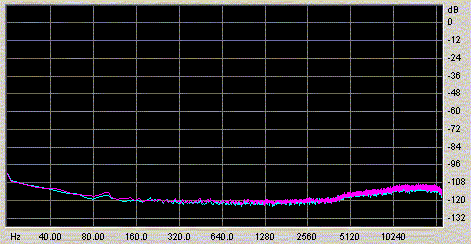
TerraTec Phase 26 ADC noise floor after necessary modifications to this unit's incompetently-designed negative voltage generator
Author: Werner Ogiers
In the first installment of this series we had a look at the noise generated at the output of a number of easy to build and cheap voltage regulators: single-chip series and shunt regs (LM317/337 and TL431), a one-transistor emitter follower, and a two-transistor discrete shunt. The investigations were done by recording the AC-coupled output of the voltage regulator, through a low-noise amplifier and a USB-coupled ADC, into a personal computer, followed by spectral analysis of the output below 20 kHz.
You may remember that the clear winners of the contest were the two discrete transistor solutions. The shunt reg's noise floor was almost undiscernable from the measurement pre-amplifier's itself, and the emitter follower did virtually the same, only marred by slight breakthrough of 50Hz mains harmonics.
Well, not anymore. That mains breakthrough was the result of direct induction from a nearby unshielded toroidal transformer. Moving the (also-unshielded) voltage regulator mere decimeters away from the transformer revealed the same low noise floor as the shunt reg.
Another thing that slightly disturbed the noise articles was a strange 10kHz noise bump, self-generated by the Terratec Phase 26 outboard ADC/DAC used. I investigated this further, and found it to be a very stupid and shameful design error, inherent to this otherwise fine component. I defined a hack that more or less cured this fault, at least for sampling rates below 48kHz, more of which you can read in a short report I posted at www.diyaudio.com.

The rising noise floor below 80Hz is another display of TerraTec's expertise. I was able to tackle this too, see spectrum plot below. It may be of interest to that company's bean counters and 'design' staff that the total cost of my fixes amounted to two 1/8W resistors and one 22uF capacitor. (If you guys and dolls read this: I may want to tell you where to put these components, but only if you ask me real nice.)
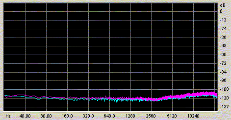
Let me conclude this business by relaying that the fault as well as its probable cause have been reported to Terratec months ago, and by several people independently, and that this company so far has done not a single thing to remedy this or to apologize for it. A truly sorry state of affairs. I hope to lay off my Terratec soon enough, in order to buy a standalone PC with a true sound card, the Lynx L22, which surprisingly doesn't cost that much money at all, or the RME FireFace 800, which is overkill, but offers the FireWire connectivity so needed by laptop users.
But enough whining, back to business ...
Output impedance is the combination of resistance and reactance a regulator, and any capacitors and bypasses attached to it, presents to the voltage rail it regulates, and to any load attached to it. It is the supply-side equivalent impedance as traversed by the load current when on its loop from supply voltage, to load circuit, to ground (through the load), and up into the supply again.
Why should we care about it? As said, the load current I passes the regulator impedance Z, and according to Ohm's law develops a voltage U = Z x I over it. In most audio circuits the load current is either related to the signal itself (as in amplifiers), or is plainly dirty (as in logic circuits). Either way, the voltage over the supply impedance is an error term, and should (almost) always be as low as possible.
Why that, then? Because amplifier circuits tend to have a finite power supply rejection, meaning that they do not only amplify their input signal, but also, to a lesser extent, the signal carried by their supply rails. So the output of the amplifier is a complex sum of its input signal and whatever is riding its supply rails.
This does not matter that much when each regulator is only feeding a single gain stage, but you understand that it all becomes a mess when the regulator is supplying at the same time any number of amplifiers, channels, circuit types, DAC chips, and perhaps even logic too. The nasties this generates are a form of crosstalk, and depending on the precise nature of things, crosstalk with a lot of distortion and intermodulation to it. We don't want this, so again: in general we want the regulator's output impedance low (for a low error voltage), with good linearity (for low distortion of the error voltage), most certainly non-resonant (i.e. emphasizing specific frequencies), and perhaps even purely resistive.
As I'm not equiped to measure output impedances, the following sections are entirely based on circuit simulation of our four main regulator types. This simulation was done with Catena SIMetrix, a rather good Spice-like program of which a decent evaluation version can be downloaded freely. As always with simulation, the models used aren't quite the same thing as good old reality, and we are here entirely at the mercy of the existing approximate models of semiconductors. But even more, passives tend to be of the 'ideal' persuasion during simulation. This is of little consequence with the resistors in our little story, but capacitors, and especially electrolitic caps as often used with voltage regulators, are a different kettle of fish. I added to the ideal simulator capacitances values of ESR (equivalent series resistance) that are, if not quite real, at least realistic. I could not do such with ESL (series inductance), as cap suppliers tend not to specify ESL in their datasheets, and anyway, the total parasitic inductance depends too much on the actual board layout to say anything meaningful. So, with the cap's inductance entirely left ignored, and with varying degrees of suspicion around the actual regulator and transistor models used, this means that the following results grow increasingly less trustworthy above, say, 100kHz, and induce not much confidence anymore at above 1MHz.
But what there is is enough to show the trends and to give a general idea of what's happening, impedance-wise.
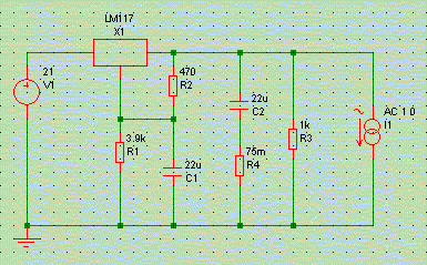
The above schematic is the simulation setup. Most of the diagram you'll recognise from the noise article. R4 models output capacitor C2's Equivalent Series Resistance (ESR), with a value of around 100mOhms common for medium-Z capacitors of around 100uF, with more ESR for lower-value caps. Resistor R3 constitutes the load, pulling about 12 mA from the regulator.
I1 is a frequency-dependent current source, forcing a current sweep of 1 Ampere from 1Hz up to 1MHz around the circuit loop. Doing so reveals the supply impedance simply by measuring the AC-component of the voltage on the supply rail, as U=ZxI, with I=1. So while labelled in 'Volts', the following graphs should all be read as 'Ohms'.
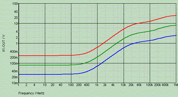
The output impedance of the LM317, even at DC, depends strongly on the load current, with impedance dropping with increasing load. This is not new, and it is precisely the reason why it is always recommended to ensure that such a regulator chip sources at least 10mA, preferrably 30mA, no matter what the actual load demands. At 100mA and more the impedance goes as low as 30mOhms or so, turning inductive above a low 400Hz. This is typical for a circuit relying on loop feedback, using an error amplifier with not a lot of gain and not a lot of bandwidth.
All of the following graphs were made with 10mA load current.
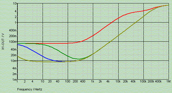
Just as it improved noise, so does bypassing the adjustment terminal with capacitor C1 bring tangible benefits to the impedance, at least in the lower frequency regions. The inductive (i.e. rising impedance behaviour) above 400Hz is not cured. In what follows we adopt C1=220uF.
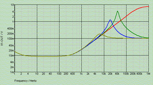
Adding an output capacitor, C2, effectively bypasses the regulator at higher frequencies. As the LM317 is inductive in these regions, this makes for a resonant circuit and hence some damping in the shape of a not-too-low capacitor ESR is called for: it is good to follow LM317s with a relatively big cap, but it is bad to use a low-Z cap there!
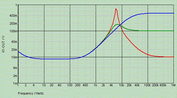
How bad exactly is shown above. The hypothetical 220uF/10mOhms capacitor gives rise to a massive resonant peak at 5kHz. The equally-hypothetical 1000mOhms cap yields no resonance at all, but neither does it do anything useful.
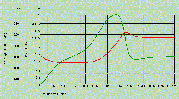
So far we have concentrated on the magnitude of the output impedance. Above plot gives magnitude for our typical case, alongside the electrical phase of the impedance. Even confined to the 20Hz-20kHz band does the phase swing over 80 degrees, making the voltage rail appear highly reactive.
Another interesting thing is the influence of board layout on a regulator's performance. We'll investigate this now just for the LM317, but what follows is equally valid, mutatis mutandum, for just about any other regulator.
Consider the following two wiring topologies. For the sake of argument we have replaced the ground wires with resistors of 1 Ohm each. This is an exaggeration, but it will help us visualize the differences in performance between circuit wiring strategies.
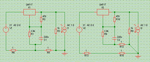
The left circuit has the regulator and its configuration network spaced from the load by a to-wire and a from-wire. It is obvious that the load current passes both wires, creating voltage drops over them. Now, the circuit being what it is, the ground connection of the LM317's adjust network does not 'see' the load's ground potential anymore, rather, it sees a ground polluted by the voltage drop of load current over the ground wire.
The right circuit has a twin ground connection: the lower one carrying the return load current, and the upper one carrying (almost) no current, but connecting the LM317's adjust network to true load ground.
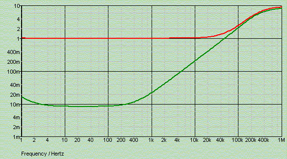
The impedance plot is telltale: the incorrect wiring scheme makes it impossible for the regulator to compensate for the ground return wiring's impedance, and hence it all adds to the regulator impedance. The correct wiring scheme just compensates the ground wire impedance, and presents the LM317's innate impedance to the load. As it ought to be.
How many of the hifi industry's outboard power supplies are properly implemented, do you think?
Troublesome, then. And not only in our hobby ...
A job story: A couple of weeks ago a junior ASIC design engineer here at F*llFactory went into the lab to characterise a new chip we made for ultra-low noise radiation-hard aerospace applications, plugging it into a PCB custom-designed by the engineering dept. After a while he came out, totally despirited: he had tens of millivolts of 30kHz ripple on about all of the chip's regulated supply lines. Try to measure device noise limits under those circumstances...
I came by and investigated: the device under test was drawing pulsed packets of 100mA from one of its supplies, at a repetition frequency of 5kHz or so. So far so good. But that supply line, and all the others, was controlled by an LM317 loaded with a 1uF low-Z ceramic cap nearby, and a dozen of 100nF caps distributed around the big chip. With about 2uF of low-ESR capacitance it was no wonder at all that this particular regulator was prone to oscillation. And the chip's current draw profile only exacerbated things. Trashing the ceramic cap in favour for a big ugly and cheap 100uF elcap entirely cured the problem and left the supply stable and of relatively low noise.
I wrote a short and fiery memo to the engineering dept.
The morale of this story? If you see an LM317, or about any other three-leg regulator for the matter, chances are someone already did a perfect job of screwing it up for you.
© Copyright 2004 Werner Ogiers - www.tnt-audio.com