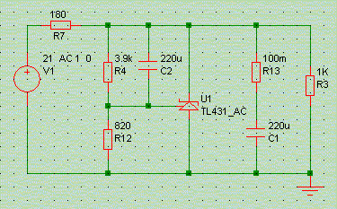
Ripple-rejection measurement setup example
Author: Werner Ogiers
In Part 1 of this series we looked at the output signal of voltage regulators caused by noise, i.e. the output generated by the regulators themselves, irrespective of the load or the raw supply. In Part 2 we looked at the output impedance, which is a measure of how the regulator reacts to varying current draw from its load. In this third part we have a quick look at how a regulator succeeds in suppressing any AC signals that are riding on its raw voltage supply input: power supply rejection or ripple rejection.
Ripple rejection is important as in all cases (batteries excluded), the raw supply is polluted by 100/120Hz rectifier pulses, their harmonics, and whatever RF that has been picked up by the mains. Nothing of this is supposed to make it right through to the audio circuits.
Sure, the main reservoir capacitors found after the rectifiers filter out some of this, but not quite all: these capacitors generally are large, bulky, and have a high ESR and ESL that precludes them from being very effective at higher frequencies. Moreover, in order to filter, a circuit has to consist of series resistance and shunt capacitance together, while in most power supplies the main capacitors directly follow the rectifiers, and as such have little R in front of them.
(As an aside, for circuits with low current demands such as DACs, phonostages and preamplifiers the classical raw supply setup of transformer, rectifier, and reservoir caps is decidedly ill-advised: the caps have little filter action, and due to their high capacitance they force the loading current from the transformer/rectifier to come in very high peaks of very short duration, a veritable source of induced pollution further up and down the supply line. It is sooo much better to follow the rectifier with a suitably-scaled resistor (or inductor!), then a small capacitor, and then a bank of RCRC filters with low-value Rs and high-value Cs. This scheme has a wildly superior filtering of ripple. The only drawback is that due to the subsequent losses in the series resistors or inductors a transformer with higher output voltage must be chosen, but against this can be put its much more benign charging current behaviour, that allows a transformer with lower current of VA-rating to be selected. End of rant.)

The little circuit example above indicates how to simulate for ripple rejection. The raw suppy source now comprises of the usual 21V DC, with a 1V AC component superposed onto it. This AC component is swept from DC to 1MHz, and the signal at the regulator's output is recorded, in decibels (dB). The reference is 0dB, corresponding to the unattenuated AC level at the reg's input. So the traces recorded directly indicate ripple rejection versus frequency.
The following plot has the results for our four main types of voltage regulator, all connected to a 220uF / 100mR output capacitor. Both the shunt regulators have a 180 R resistor as their series dropping element, chosen to allow 15mA delivered to the load, and 15mA consumed in the shunt, for a 15V output voltage.
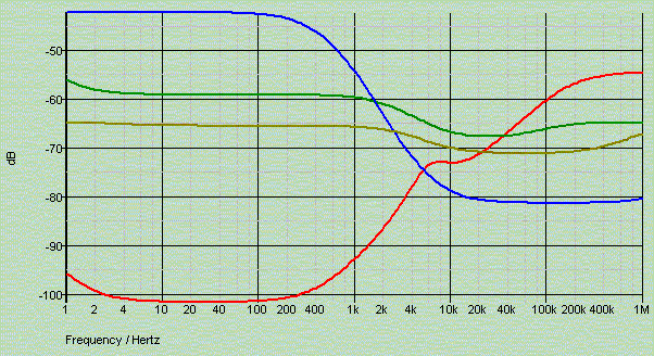
The superiority of the LM317 is clear: it is the only high-gain high-feedback component of the lot, and by sheer corrective action it succeeds in annihilating ripple below 400Hz. The circuits with less gain do markedly less, and our poor emitter-follower fares outright badly. However, above 1kHz these simple circuits get somewhat better as the filtering action of their 220uF output capacitor (if present!) kicks in.
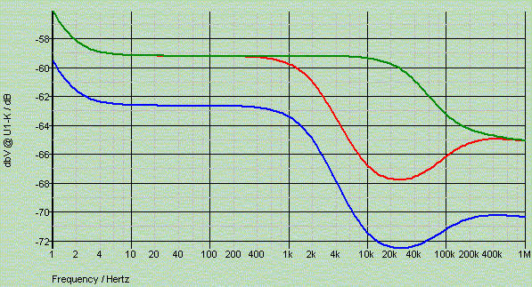
Shunt regulators have an innate series resistive element, in our case R7, which always combines with any output capacitor C1 to form an RC low-pass filter and hence reduce ripple for higher frequencies. This also means that, contrary to an all-in-one series regulator such as the LM317, the ripple reduction of a shunt reg depends both on the regulator type and on its specific implementation, i.e. its ancillary components.
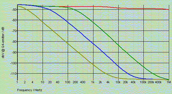
In the above traces the values of R7 and C1 are varied to obtain three regulators, all with 15V output, but with differing ripple performance.
Now a closer look at the high-gain two-transistor shunt reg that did so wonderfully in the output impedance contest ...
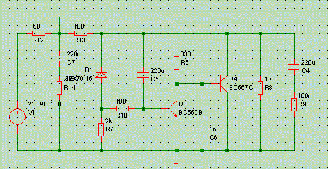
As was said before, you win some, you loose some. In this case ripple reduction suffers badly, and in fact this regulator has the worst performance of them all in this respect, not even -50dB over the full bandwidth (see bottom plot, red trace).
The reason for this is easy to spot: gain transistor Q3's collector load is connected to the point between the twinned series dropper resistors R12 and R13. This directly exposes the circuits error amplifier to the ripple we want to suppress. A lost case ...
Luckily there is an easy solution: connecting additional capacitor C7 between the intermediate voltage supply and ground passively filters the ripple present there, aided by the presence of R12. This capacitor should be large (see the gold trace in the plot for the effects of 2200uF), and preferably of the lowest ESR and ESL possible.
© Copyright 2004 Werner Ogiers for www.tnt-audio.com