[ Home | Staff & Contacts | HiFi Playground | Listening tests | DIY & Tweakings | Music & Books ]
Product: DIY SET6080 Amplifier
Manufacturer: You dear reader
Original parts supplier: World Audio Design - still trading but link may not open as is shown often as www without latest https prefix
https://www.world-designs.co.uk/
this url only seems to open using duckduckgo so that is what the plebs must use, while lurking stage left
Contact:sales@world-designs.co.uk
Price: Your mileage WILL vary - it's all up to you what parts you specify
Author: Mark Wheeler - TNT-Audio UK
When: Created, modified, modified again & again, & again and continually reviewed: 1997- today, 2025
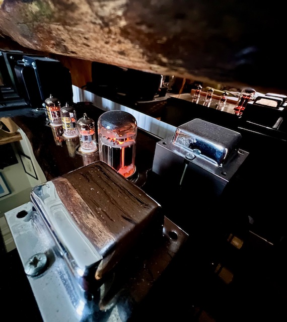
Your Old Scribe was looking for a simple design to execute from scratch to explore the delights of single ended triode amplification, as you will recall from Part 1. Having read Jean Hiraga's, Allen Wright's and Hiroyasu Kondo's articles/white papers; and every issue of Sound Practices from the first, I was curious. Here was a different way. On this occassion plumbing the depths does not mean bass from the crypt but the subtlest micro detail from the lowest volumes. Here was an obsession with downward dynamic range rather than the top of the audio transfer characteristic. This might be especially useful in the midrange and treble sections of an active moving coil loudspeaker system.
“Oh no!” Exclaim plebs, stage left, “Lookout! There's an impending motoring or photographic analogy on the horizon.”
Because big reserves of current for bass duties are less important than low noise and clean treble our amplification priorities are changed. Here we are exploring ideas about the bottom of the amplifier transfer characteristic. This S curve, just like in analogue film practice, is all about what happens with the fewest electrons. In film exposure and development, as the lowest light levels approach 'Film base plus fog', we are concerned with preserving the subtlest details by minimising noise and losses. In the zone system this is the equivalent of shadow detail, of correct exposure and of avoiding over development. It's about communicating through subtlety, with depth and nuance.
In analogue film terms big power amplifiers (whether valve or transistor or class D) are the equivalent of developer chemistry. This is, in our analogue film analogy, all about the chemical concentration, the temperature and agitation of the developer to push the top of the S curve higher. Like film, this can end up increasing artefacts like crossover distortion, the equivalent of increasing film grain and film base plus fog, thus losing subtle detail. The photographic equivalent of the Single Ended Triode (SET) philosophy is about getting the best shadow detail, like a zone system perfect exposure of a single sheet of low speed film.
“Enough already!” Insist exasperated plebs, stage left, “Get on with the amplifier design.”
Knowing the context that we are going to use any amplifier can dictate our design more precisely. This amplifier will never have to drive a passive crossover complex load. This amplifier will never have to reproduce dance hall bass. Direct coupling to a high resolution tweeter will expose any problems with breakthrough ripple, hum, crossover distortion or intermodulation distortion. So this context should be paramount in decisions about size and type of smoothing/storage capacitors in the power supply.
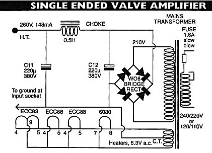
Because this design uses a solid state rectifier we will have to ensure that there is no noise caused by overshoot. This could easily be avoided by using a valve rectifier or a valve regulator but I intended to start from the design topology as published. The low transient power demands mean smoothing is most important rather than energy storage and recovery. This permits quite modest capacitors in the filter, especially because there is a choke in the power supply pi filter. This inductor has additional smoothing and noise advantages over a resistor.
Any amplifier is merely a modulated power supply. The electrons at your loudspeaker terminals are not the same electrons at the input terminals made bigger. The input signal of an amplifier merely controls the flow of energy from the power supply to the loudspeakers. Hence an inadequate power supply with poor regulation under load and poor smoothing will a poor amplifier make, however clever the signal circuit. The power supply is the context in which the signal circuit operates.
There is a fallacy that any old power supply with reasonably low ripple will do if the the 'audio circuit' has a reasonable Power Supply Rejection Ratio (PSRR). Deconstructing that term indicates why this idea is a fallacy. The audio circuit has a PSRR, a Power Supply Rejection Ratio. It is a ratio not an absolute, so a better power supply will always deliver better audio. The power supply quality is described in terms of three quantitative dimensions:
In this application there will be no big current demands when amplifying big bass signals because this amplifier will not be amplifying anything below 200Hz. Big bass demands a big power transformer, rated well above the theoretical circuit steady state demand and 30%-100% derating is typical practice in the audiophile world. This baby SET is usually going to be in locations operating above 1kHz. So regulation demands are at the higher frequencies, which means lowest ripple and lowest impedance at high frequencies. These affect size and choice of smoothing capacitors. All of this is beautifully explained with simple formulae, in the RCA Radiotron Designer's Handbook. Every valve/tube amplifier designer, and even owners, should own a copy of this book. Hard copies now cost upwards of €40, cdrom copies for a tenner and downloadable pdf for free. You have no excuse. Part 5 of this wonderful tome contains all you need to know about power supplies and the microphone section is perfect for phono and line pre-amps which is equally ideal for the low ripple we need in a treble amplifier.
Obviously the mains transformer is the first of these devices involved. The original kit supplied a good quality mtx with two secondaries, one for HT and one for valve heaters. Transformers are heavy to post so your local suppliers would be a good choice. Most will have a suitable two secondary design off-the-shelf and if you choose higher VA rating, the the regulation will be better, all other factors being equal.
Smoothing in this PS design is by the traditional CLC Pi filter. The 220µF size is more than enough and there is a classic Cerafine NOS 220+220 that would be perfect if you have the budget; your Old Scribe has one of these saved for a phono pre-amp project but not for the SET6080. I used some bypassed BHC slit foils which work fine. Bypassing is especially useful in a treble amplifier because, other factors being equal, smaller capacitors tend to have smaller ESR (Equivalent Series Resistance) at higher frequencies than big ones. We need big ones for minimum ripple so we bypass them with smaller ones. There used to be a 1/100 rule so that our 220uF capacitors would be bypassed by a 2.2uF cap, bypasses by 0.022uF, bypassed by 220pF. The zero feedback single ended purists argue that this all results in what they call “diffusion” and recommend massive Black Gates costing several hundred Euroetc. Your Old Scribe has undertaken many permutations and combinations of numerous capacitors at many budgets. The conclusion is that neither of these exotic approaches make a noticeable difference in the power supply but that a single good quality bypass capacitor is as good as either more obsessive approach. In this case a 1uF 630V film type will suffice.
Using an inductor (historically referred to as a choke in valve amplifiers) between the capacitors reduces power supply impedance, reduces resistor noise, and reduces ripple compared with a resistor. This design uses a 0.5mH (which is perfectly adequate, especially for a treble only amplifier) but most suppliers can offer a range up to 5mH inductors for this purpose. There is no need for the expensive 'choke regulated' type here because the first capacitor loads the rectifier. Bass quality can proportional to power supply size, so remember that if this is to be full range.
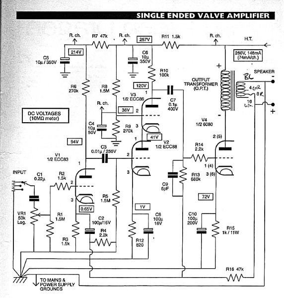
Experiments with other amplifiers have demonstrated your Old Scribe's preferred modus operandi in teerms of regulators in power amplifiers. This amplifier design already fits that pattern, with a fairly stiff supply to the driver ECC88 valves created by the cascode configuration. The cascode arrangement means that the 6080 demands on the HT B+ rail do not affect the regulation of the driver valve supply. This also means that this is a 3 stage amplifier despite the four valves (tubes) and is therefore inverting. Reversing the connection to the loudspeaker terminals restores absolute phase. The local power supply bypass capacitors C5 and C6 (10µF bypassed with 0.01µF) maintain short term demand wrt to the output transformer primary demand on the HT (high tension) rail via the resistors R11 and R7.
Your Old Scribe built the power supply and tested it on a breadboard. Fast recovery diodes were soon substituted for the basic bridge rectifier after experiments revealed that the bridge was generating its own HF noise. The heater secondary was producing a clean sinewave requiring no further action. Under load, the scope trace looked cleaner when zoomed in once the aforementioned 1µF bypass capacitors were added to the 220µF BHC slit foil caps. Some people bypass the rectifier diodes with small capacitors to nail any overshoot noise. There was none measured from the fast recovery diodes so this seems superfluous.
![]()
© 2025 Mark Wheeler - mark@tnt-audio.com - www.tnt-audio.com
[ Home | Staff & Contacts | HiFi Playground | Listening tests | DIY & Tweakings | Music & Books ]