Product: TNT InDiscreet phono preamp
Company: not for sale, TNT-Audio free DIY design
Approx. cost: 50-75 $/Euro (just components)
Author: Giorgio Pozzoli - TNT Italy
Published: March, 2003
I can nearly hear your voices: "Another phono stage! and this is the third one! No need for another phono stage."
Perhaps you are right. But on one side Lucio asked me for a very low cost phono stage. On the other I wanted something that could dig more deeply into my vinyl. And finally I definitely wanted a better design than the previous ones, given my mild and not superb at all character...
So this is the result: a rather simple, but for sure peculiar, solid state phono stage with two different power supply options: battery (with charger) or normal.
No revolution, anyway: all of the techniques used are definitely well known, even though hardly used.
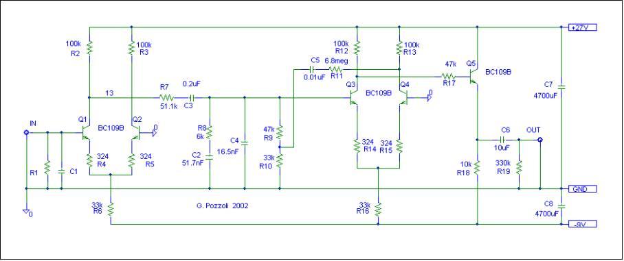
The schematic is rather simple: the first stage is a basic transistor differential amplifier, with some local feedback; after this there is a classic passive RIAA network, followed by another transistor differential amplifier with some local feedback and an emitter follower to reduce the output impedance.
Nothing more than this, apart a small amount of feedback from the output to the input of the second diff amp. Horrible, you'll say - input/output feedback where it is not needed, but far worse then this: this is positive feedback, not negative!!!
OK, now you are thinking I have designed the first phono oscillator in the history. Not true, in fact I am sure I am not the first one. Many years ago some positive feedback was applied in another phono stage - it was called Pulltech. If you've never heard about it you'd better do some research, because the myth that the Pulltech was not a special design is just that. It was especially known for its high dynamics... there may have been many others doing the same, but I do not know. What I do know is the Pulltech circuit was considered rather tricky to set up...
Coming back to the schematic, initially I reduced the feedback amount at high frequency with a low pass filter, just to avoid any stability problem. As a matter of fact, I never had such a problem, so the filter has gone.
The effect of this small PFB amount is to provide an exceptional impact to the sound: it is really much more lively, punchy and rhythmic. When I first added the positive feedback to the prototype I asked my wife just coming in the room if she found anything different in the sound and she immediately answered that it was more lively, without even paying any special attention to the sound!
This could be seen as a non-orthodox approach to sound reproduction and high fidelity, like using an expander. The point is simply wrong: from a technical point of view this is not the same at all.
I'll try to keep it very simple.
An ideal amplifier is a linear circuit: this means that doubling the input at a given frequency, the output doubles too. Note that this does not grant that the output signal has the same waveform of the input one, because does not requires a flat frequency response: a low pass filter is a linear circuit, for example, and if you pass a square wave through a low pass filter the waveform gets rounded up. Feedback is ideally a linear operation, too.
An expander instead is not a linear circuit: to increase dynamics, if you double the input, the output increases more than the double.
Our circuit is a linear circuit, so must not be confused with an expander. But what is the effect of positive feedback, then?
Well, any linear circuit has a characteristic named stability margin: as the name suggests, this indicates how far the circuit is from oscillating.
If you design a circuit for the best stability margin, often this means to make it a slow one, and in some cases the best way to make it faster is to reduce its stability margin. This is what has been done in our phono stage.
If the stability margin is insufficient, obviously the circuit becomes an oscillator (perhaps a little intermittent, thereby not a very good one...). But in our case this does not happen: I have never been able to detect any kind of auto-oscillation, and from simulation the stability margin reduction seems minimal.
So what we have here is a very fast and musical amplifier with a good stability and a lot of impact. Any problem with this?
The overall gain is very high, and the noise floor very low. I tested it with both normal output MM phono cartridges and with 2mV output MC cartridges with very good results. It can be used also with medium-low output (0.3mV) MC cartridges, but at these levels the noise floor can be detected during "pianissimo" in low noise classical recordings, even though it does not create real listening problems at all.
Finally, note that a few non standard value components present in the schematic are in practice obtained by placing two standard values in parallel:
|
R8 |
12k//12k |
|||
|
C2 |
0.047uF//4.7nF |
|||
|
C3 |
0.1uF//0.1uF |
|||
|
C4 |
15nF//1.5nF |
It is suggested to connect Q2 and Q4 transistors bases NOT to the ground plane, but to the channel ground line near C1 and R10 respectively
The phono stage was originally designed for battery operation, so a low current consumption was a mandatory point. As a matter of fact, the current is around 7mA, which is rather a low value (by the way, are you thinking it should be producing a slow and weak sound, with such low current draw? I was just thinking the same, before I listened...).
This helped a lot in allowing the use of a rather simple and not so much in fact power supply, even though with very special characteristics.
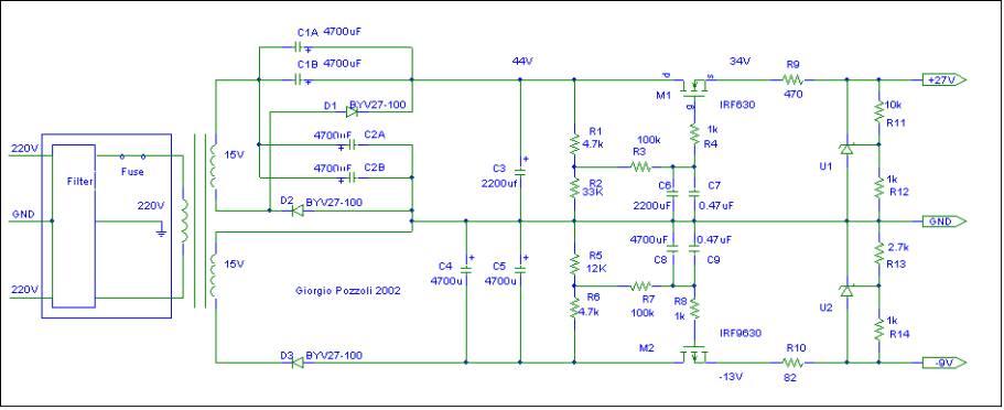
First problem, the circuit requires a dual asymmetric power supply voltage. In order to avoid the cost of two different power transformers, or the difficulties in finding a low power transformer with a dual secondary voltage of 30V (it is not so easy, you know?), I decided to use a voltage doubling rectifier circuit for the positive supply voltage (the highest) and a normal one for the negative.
Just to give the two sides... equal opportunities of introducing a good amount of ripple, both circuits are reduced to the minimum: three rectifying diodes (fast recovery) in total. Even though the filter capacitors are not huge, the ripple is reduced because of the low current required.
Anyway, the few tenths of millivolt ripple coming out of the capacitors are taken care of by two voltage regulators in cascade on each power line.
The first regulator is a simple capacitance multiplier using a MOSFET. The MOSFETs gate voltage is kept nearly fixed by a RC filter (C6-C7-R3 and C8-C9-R7) with a very large time constant (220sec and 470sec respectively: it takes 20 and 40 minutes to get to 95% of the final voltage...). The output voltage is programmed by the voltage divider (R1-R2 and R5-R6).
An N-channel and a P-channel power mosfet, IRF630 and IRF9630, are used - almost any other power mosfet of the same channel type would do. Note R4 and R8: they are gate stoppers, resistors placed as near as possible to the gate in order to kill any possible self-oscillation. In case you hear motorboating noise, move the resistors nearer to the gate pin and/or raise the resistors value.
The second regulator is based on a very common (at least in audio) shunt regulator IC, the TL431. Its behavior is very similar, as per the schematic symbol, to a programmable, precision zener; its dynamic impedance is of the order of 0.2ohm!
The integrated circuit works in such a way that the voltage between the anode (the lower terminal in the schematic) and the reference (the central connection wihch has a very high impedance) cannot get higher than 2.5V. The current in the resistor (R12 and R14) placed between these two points is therefore fixed, and you can program the "zener voltage" just by placing a further resistor (R11 and R13) between the reference and the cathode: the regulated voltage Vreg calculation is as follows:
Vreg = ( 1 + R11 / R12 ) * 2.5v
One more resistor (R9 and R10) is required to create a drop from the input voltage to the regulated one; care must be taken in order to be sure to leave enough current flowing through the integrated circuit without exceeding its maximum power dissipation.
With such a double regulation no risk of any power supply ripple going through to the phono stage exists!
Well, as I wrote before, the phono pre-amp can be optionally battery powered. Battery and battery charger completely substitute the mains power supply described above.
The original idea was to use a low cost battery, so NiCd 9V batteries were selected. At present time I am no longer using them: a series of four is not inexpensive in the end. A great advantage to Lead Acid (Pb) batteries is the size: the 9V batteries can fit inside almost any case and take up much less room than the NiCd equivalent.
One more consideration. The unit has to be on all the time, in my view, and this means more than one charging cycle a day. The battery charger has been designed to make it possible for the phono stage to work while batteries are charging, as the opposite would have meant to have the unit unavailable when needed. So in the end the battery life was far lower then expected, the batteries cost not so low, and what's worse their benefits have not been evident so far at all!
Wrap-up: the battery charger is here for whoever really wants to experiment with a battery powered phono stage. For everyone else, the mains supply is recommended. Clear?
I can hear scarcely any difference with the battery charger active or not (only a very small amount of hum with the head near the loudspeaker and the volume set to the maximum, a level definitely impossible to use in practice). Anyway a switch (SW1) to completely cut the battery off the battery charger is provided. There also is another trigger switch (SW2, a button normally open or equivalent device) to restart a charging cycle at any time.
The reason for the high immunity from hum is for sure the presence of the batteries in parallel to the power supply, and possibly also the fact that it is a constant current, high impedance power supply.
Note that the power supply and battery charging unit is floating with respect to ground, and is grounded only through the battery; anyway it is easier to analyze the battery charger circuit using as a reference the negative power supply rail.

The rectifier and regulation are really basic ones: because of the presence of the battery they should have scarcely any effect on sound. VR1 sets the regulated supply voltage (at least 44-45V). Power consumption when the battery is charging is in the order of 25-30mA.
Looking at everything from the point of view of the PSU, the battery is connected to the positive power supply rail and has a voltage controlled constant current source connected between its negative pole and the negative power supply rail.
At full charge the current source is off. A FET input op amp, U2, compares the voltage of the battery negative pole with a level that can be preset with the VR2 trimmer. When the battery negative pole voltage increases too much with respect to the negative power supply rail (that is the battery voltage decreases too much as the battery gets exhausted), the constant current source is switched on. As an op-amp I used an LF356, a very old unit I had in the junk box; any other FET input amp should work, but look below to the note about D2.
The comparison system has an hysteresis built in (note the positive feedback on U2 by R2): if the current source is active (the op amp output is of a large positive level), the battery level required to switch the current source off is far higher than the one required to switch the current source on when it is off. In this way the battery is subject to continuous charge-discharge cycles, as required.
VR3 controls the battery charging current: note that part of the current through it anyway does not go to the battery, and that part of the current is also drained by the pre-amp circuit: the best solution to set the current precisely to the required value is to disconnect the battery positive pole and measure the corresponding current. The total current required in my case is around 25mA.
Note also D2 and D3.
D2 creates a regulated supply with a voltage safely acceptable for any normal op amp: the positive rail voltage is at the limit for +-22V op-amps, so D2 reduces the 43.5 volts to about 36.5V, with a wide margin; if you use an op-amp with an absolute maximum power supply voltage of +-18V, it is necessary to increase the D2 zener voltage to 10V.
D3 instead shifts the battery negative pole voltage to a higher voltage range that can be easily managed by the op-amp input. As a matter of fact this solution is mandatory, as most op-amps are not able to correctly compare voltages that are too near the power supply rails.
To set the correct charge end threshold voltage you should set up all the other regulations as described before and then move VR2 completely to the negative rail and restart the charging cycle. In this way the charging will continue indefinitely. After the amount of time required by your batteries, you should move VR2 slowly back to a central position, stopping as soon as the charging process ends. Check again that everything is correct by retriggering the charging cycle: as the battery is already fully charged, the cycle should end automatically in few minutes or even seconds.
A far simpler, but far less handy, solution could obviously be to use an external battery charger. Take into account that the full charge in theory lasts a few hours, as you will soon discover. As a matter of fact, the battery here is not so much more than a luxury, extra-large capacitor, giving some authonomy from external, noisy power supplies.
The two power supply bypass capacitors in the phono stage could appear unnecessary. In fact I added them just to stay on the safe side, but later when I found a very different noise floor in the two channels, I was very surprised to discover that the higher noise was due to one of the capacitors being incorrectly connected. So according to me it is definitely mandatory to install them.
The prototypes are two box units, with a shielded cord between the two boxes. The cord is soldered at both ends to the boards.
The mains power supply version has the phono stage in one box and the power supply in the other.
The battery powered version has the phono stage in one box and the battery charger in the other, but the batteries are inside the phono unit box.
In both cases the cord shield is connected to ground only on the phono box side. There must also be a clamp to accept the ground connection from the turntable: the clamp must be connected to the circuit ground and the box; all the input and output RCA pins must be isolated from the box.
The phono circuit has been built on a single-sided board, whose copper side is used only as a ground plane, while the power supply is on a predrilled board. All connections are almost "in air".
A few of you wrote to me asking for some more instructions about this technique: please have a look at the assembly instructions for some more information.
When Lucio, a couple of years ago, asked me to design a low cost phono stage, I was really intrigued. My idea was to try building something really good at a really low cost.
The prototype is perhaps not in line with the original idea, as in the end some high quality components have been used - this was necessary for the circuit to be compared fairly with other high quality phono stages.
Anyway, no expensive components are really necessary to implement it. If you want, you can for example use low cost polyester capacitors instead of polypropylene, and normal RCA pins instead of gold plated ones. The two box implementation allows the use of normal transformers instead of toroidal ones. The sound will be affected, but the overall cost can really be very low (50-75 USD/Euro).
About the sound? Well, this is the unit Lucio was talking about in the review of the BlackCube + PWX. That was only a preliminary prototype, not the final version - in fact the circuit has got simpler and simpler over time, while the sound has kept on improving.
|
Qty |
Type |
Value |
Attributes |
Reference |
|
1 |
C |
100pF |
35V polypropylene |
C1 |
|
1 |
C |
0.047uF |
35V polypropylene |
C2a |
|
1 |
C |
4.7nF |
35V polypropylene |
C2b |
|
2 |
C |
0.1uF |
35V polypropylene |
C3a, C3b |
|
2 |
C |
0.015uF |
35V polypropylene |
C4a |
|
1 |
C |
1.5nF |
35V polypropylene |
C4b |
|
1 |
C |
0.01uF |
35V polypropylene |
C5 |
|
1 |
C |
10uF |
35V polypropylene |
C6 |
|
1 |
C |
4700uF |
63V electrolytic |
C7 |
|
1 |
C |
4700uF |
25V electrolytic |
C8 |
|
5 |
Transistor |
BC109B |
Q1, Q2, Q3, Q4, Q5 |
|
|
1 |
R |
68k |
1/4W 1% Holco or metal |
R1 |
|
4 |
R |
100k |
1/4W 1% Holco or metal |
R2, R3, R12, R13 |
|
4 |
R |
324 |
1/4W 1% Holco or metal |
R4, R5, R14, R15 |
|
3 |
R |
33k |
1/4W 1% Holco or metal |
R6, R10, R16 |
|
1 |
R |
51.1k |
1/4W 1% Holco or metal |
R7 |
|
2 |
R |
12k |
1/4W 1% Holco or metal |
R8a, R8b |
|
2 |
R |
47k |
1/4W 1% Holco or metal |
R9, R17 |
|
1 |
R |
6.8M |
1/4W 1% Holco or metal |
R11 |
|
1 |
R |
10k |
1/4W 1% Holco or metal |
R18 |
|
1 |
R |
330k |
1/4W 1% Holco or metal |
R19 |
|
4 |
Pin RCA |
Female |
Gold Plated, Insulated |
|
|
1 |
Ground Cord Clamp |
Gold Plated |
||
|
Qty |
Type |
Value |
Attributes |
Reference |
|
7 |
C |
4700uF |
25V electrolytic |
C1a, C1b, C2a, C2b, C4, C5, C8 |
|
2 |
C |
2200uF |
63V electrolytic |
C3, C6 |
|
2 |
C |
0.47uF Film |
63V |
C7, C9 |
|
3 |
Diode |
BYV27-100 |
Fast Recovery |
D1, D2, D3 |
|
1 |
MOSFET |
IRF630 |
M1 |
|
|
1 |
MOSFET |
IRF9630 |
M2 |
|
|
2 |
R |
4.7k |
1/4W |
R1, R6 |
|
1 |
R |
33k |
1/4W |
R2 |
|
2 |
R |
100k |
1/4W |
R3, R7 |
|
4 |
R |
1k |
1/4W |
R4, R8, R12, R14 |
|
1 |
R |
12k |
1/4W |
R5 |
|
1 |
R |
470 |
1/4W |
R9 |
|
1 |
R |
82 |
1/4W |
R10 |
|
1 |
R |
10k |
1/4W |
R11 |
|
1 |
R |
2.7k |
1/4W |
R13 |
|
2 |
IC |
TL431 |
Voltage Regulator |
U1, U2 |
|
1 |
Transformer |
Secondary 15+15V |
20VA |
TR1 |
|
1 |
IEC Power Supply Socket |
with integrated RF filter and fuse |
||
|
1 |
Fuse |
125mA |
||
|
Qty |
Type |
Value |
Attributes |
Reference |
|
2 |
C |
0.47uF |
63V film |
C1, C2 |
|
3 |
C |
4700uF |
63V |
C3, C4, C5 |
|
1 |
Diode |
BYV27-100 |
D1 |
|
|
2 |
Zener |
6.8V (or more, see text) |
D2, D3 |
|
|
4 |
Diode |
LED, colour: red |
D4, D5 |
|
|
4 |
Diode |
1N4148 |
D6, D7 |
|
|
1 |
Transistor |
2N2222 |
Q7 |
|
|
1 |
R |
1k |
1/4W |
R1 |
|
1 |
R |
47k |
1/4W |
R2 |
|
2 |
R |
10k |
1/4W |
R3, R4 |
|
1 |
R |
4.7k |
1/4W |
R5 |
|
1 |
Switch |
2 way, 2 positions |
SW1 |
|
|
1 |
Switch |
1 way, 2 positions |
SW2 |
|
|
1 |
IC |
LM317 |
Voltage Regulator |
U1 |
|
1 |
IC |
LF356 |
Fet input op amp |
U2 |
|
1 |
Trimmer Pot |
50k |
1/4W |
VR1 |
|
1 |
Trimmer Pot |
50k |
1/4W |
VR2 |
|
1 |
Trimmer Pot |
100 |
1/4W |
VR3 |
|
1 |
Transformer |
Secondary 24+24V |
10VA |
TR1 |
|
1 |
IEC Power Supply Socket |
with integrated RF filter and fuse |
TR1 |
|
|
1 |
Fuse |
125mA |
TR1 |
|
PCB's!!!: Thanks to one of our readers (Diego Pozzoli) who built the TNT InDiscreet we are now able to give you the complete schematics for drawing and making the necessary InDiscreet PCB's. Istructions and step by step procedure have been put into a single (small) PDF file
© Copyright 2003 Giorgio Pozzoli - https://www.tnt-audio.com
Supervisor: Tom Browne