[ TNT | Who we are | HiFi Shows | Factory tours | Listening tests | HiFi topics | Tweakings | Inter.Views ]
Load the Magnets!!!
47 may not be the answer to life, the universe, and everything
[Italian version]
Author: Werner Ogiers - TNT Belgium
When interfacing a moving magnet (MM) cartridge to a phono preamplifier the cartridge is generally terminated in a resistance in parallel with some capacitance. This capacitance is made up of the connecting cable's parasitic C, typically about 100pF, and any capacitance explicitly or implicitly presented by the preamp's front-end. The latter can be fixed (bad), or user-variable (good). However, the terminating resistance in the preamp is nearly always the usual 47 kilo-Ohms.
I don't know if that 47k emerged as a true international industry standard (the 1952 Radiotron handbook doesn't mention it, apparently any loading was legal then), or just de-facto became the thing a manufacturer did in order to keep his 1960-1970s mass-market turntable systems understandable and user-friendly: after all a confused consumer won't buy, and what can't be tweaked won't confuse. Hence the fit and forget 47 solution, and user-adjustable capacitance was for nerds. Even then.
But lately there has been a buzz on the 'net about alternative loading methods for moving magnet cartridges: people are urged to depart from the fixed 47 kilo-Ohms in parallel with variable capacitance, in favour of variable resistance, now with just the minimum of fixed loading capacitance.
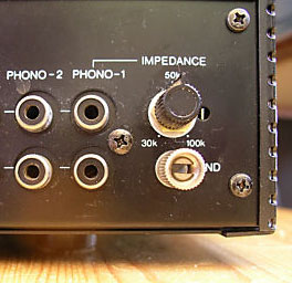 This isn't new: in 1952 the mentioned Radiotron Designer's Handbook hints at it; in 1982 the somewhat controversial dealer/manufacturer-published mag Audio Basics (re)discovered it, and at the same time some upmarket Japanese components sported loading potentiometers in their MM stages (see picture of a Luxman C12).
Today's re-invention of the same is exemplified in postings on fora (like www.vinylengine.com) and guidelines or even tools on the websites of manufacturers or audio engineers (like http://www.hagtech.com/loading.html), claiming that for each cartridge the exact fitting load resistance can be calculated.
The underlying idea or theory is that an MM cartridge can be modelled in the electrical domain as a resistance in series with an inductance, with both values often specified by the manufacturer. This equivalent circuit, when terminated in the amplifier-side shunt resistance and capacitance, forms a second-order low-pass filter, the damping (or peaking) of which is controlled by the load resistor. It is concluded that the standard 47k often gives rise to severe peaking in the audible range, e.g. at around 12-15kHz, followed by a serious loss of the high treble.
Have a look at an excerpt from Audio Basics:
The operational characteristics of your phono
cartridge can be separated into two distinct classes.
The first are the mechanical characteristics. This
class includes the stylus and suspension and its
mechanical motion and resonances, and the mechanical
resonances inherent in the body structure;
the mechanical frequency response of your
cartridge as limited by the compliance of its
suspension, the mass, length, and stiffness of the
cantilever, the polish of the diamond and its
alignment, all mechanical dips, peaks and resonances.
It is the mechanical output of your cartridge
as further modified by tone arm and turntable
resonances that is transformed into the
electrical signal.
The electrical characteristics of the cartridge can
then be considered separately making a few
reasonable assumptions:
l. An ideal cartridge should have a flat
mechanical response.
2. An ideal cartridge should have a flat electrical
response.
3. It is not likely that mechanical non-linearities
can be compensated for by designed-in
electrical non-linearities.
4. It is likely that mechanical and electrical
non-linearities are additive, producing sonic
problems worse than either apart from each
other.
5. It is probably a good idea to make the electrical
frequency response as flat as possible, no
matter what the mechanical response of the
cartridge may be (one problem is probably
not as bad as two problems).
The electrical characteristics of a magnetic cartridge
are easy to consider ...
Now the snag is that "should" does not equal "is" in our imperfect world: real cartridges do have a non-linear mechanical frequency response, due to a number of structural resonances and losses in the cartridge itself and in the springy vinyl-diamond tip system. And manufacturers do use the cartridge's electrical parameters combined with recommended load values for compensating their product's mechanical misbehaviour. Particularly MMs, more so than MCs, are a real case of two bads making one good. This can't be ignored.
So while there may be some merit in using the load resistance as an additional parameter in the cartridge-preamp interface, it seems wrong to conclude, or at least hope, that optimising the cartridge's response solely in the electrical domain also optimises the summed mechanical+electrical response.
 I wrote this article just to illustrate this, running computer simulations alongside real cartridge measurements, contrasting the electrical model world with the real world.
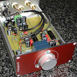
For this I lent a used but not too old Shure M97xe, a typical example of the MM breed (though lately apparently plagued by quality issues, see my TNT review as well as more recent articles and correspondence by J.LeSurf in Hifi News). The manufacturer states its generator impedance as 1550 Ohms resistance plus 650mH inductance. This was connected to my latest homemade phonostage, a little thing I designed for utter flexibility: it has an extremely accurate RIAA response, a continuous gain range from 30dB right up to 70dB, and it can load the cartridge with any capacitance over 50pF, and any resistance below 100k. Ideal for this experiment.
If we model the M97's generator in the electrical domain, together with its Shure-recommended load of 47kOhms and 250 picofarad, we get an equivalent circuit and simulated frequency response like this:

We see an almost flat response out to 10kHz, with a 0.5dB lift at 8kHz, and a severe treble drop, -4dB at 16kHz and even 8dB down at 20kHz.
Would the M97xe loaded with 47k // 250pF and measured in the flesh match this? The following is a frequency plot taken from a 44.1kHz recording of the blue Hifi News & Record Review Test Record pink noise track, using a 1024-point FFT.
Above 2kHz the response tapers down to a -3dB level at 6kHz and then remains flat to beyond 16kHz (note that the readings above 16kHz should not be trusted with this test record). No peaking at 8kHz, no severe treble loss above 10kHz. Clearly the electrical model is not telling us the whole story: the all-to-real midrange losses are not predicted, and there must be a mechanical resonance above 12kHz boosting the whole treble level in order to compensate the treble droop due to the loading.

Now let's vary the load resistance, while keeping C at 250pF. The above simulated plot gives the electrical responses for 47k, 75k, and 100k. A pronounced resonance at around 11-12kHz develops and reaches a peak of 5dB in the 100k case. After this treble rolls off again.
The real-world cartridge then yields this:
There is now indeed some marked peaking, although at 13kHz or so, and in the case of 100k loading reaching a peak level of only 0.5dB relative to 1kHz, contrary to the +5dB predicted by the model. Observe that with 250pF and 75k loading the high treble is roughly at the level of the 1kHz reference. Let's adopt this 75k load now as 'better' than the standard 47k ('better' because we get 'more' treble, something the M97 au naturel lacks) and see what happens when we vary the load capacitance between 150pF and 370pF:
Increasing the load capacitance predictably lowers the resonant frequency and reduces the damping, hence more lift to the midrange and higher peaking. Would the latter suffice to equalize the M97's annoying midrange droop?
The 75k // 370pF case is the flattest, but only extends to 14kHz. The 75k // 150pF case has the widest treble response, but this at the cost of a deeper midrange suckout. Now tell me, which loading will sound the best? Answer: there is no best. Taste will dictate. Which suggests that any closed formula for this problem is indicative at best, and misleading at worst.
Conclusion
While bringing resistive loading to the set of user-adjustable parameters in the MM cartridge-preamp interface clearly adds a useful degree of freedom to the sound optimisation problem, doing so purely on the basis of the cartridge's electrical specification and attempting to flatten out the electrical frequency response is ill-advised.
Both electrical and mechanical aspects must be incorporated, and this means measuring the real thing, or failing that, listening to it. Or vice versa of course.
Lab rats and stuff
- turntable: Michell Gyro SE with subchassis-mounted Maxon DC motor and DIY 'm:machinery' supply
- tonearm: Rega RB-300 with Incognito wiring and Michell Tecnoweight
- phono preamp: DIY 'KlangwerK'
- signal analysis software: Adobe Audition 1.5
- electrical circuit simulation software: SIMetrix 4.2b
- background music courtesy of: Apple iTunes, Terratec Phase 26USB, Fostex PM0.4 active monitors
- furniture: cheap IKEA office chair
|
© Copyright 2008 Werner Ogiers - www.tnt-audio.com
[ TNT | Who we are | HiFi Shows | Factory tours | Listening tests | HiFi topics | Tweakings | Inter.Views ]