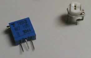
Sealed multiturn trim pot on the left, commercial junk pot on the right
I don't know why, but over the last few years there seems to be a race on among the manufacturers of audio in the low and medium class. They all seem hell- bent on finding the absolutely cheapest and worst trim potentiometers on the planet. When satisfied they got the worst possible, they happily solder them inside their products.
Far too many products I have seen over the last few years have had their trim pots degrade to unbelievably low levels of operation after a year or two of service. Being generally quite open, they are highly susceptible to common house dust, which slowly settles on them and degrades the initially not too good a contact, and your possibly being a smoker certainly doesn't help. The result is anything from deteriorated to damn poor performance from otherwise solid units.
To appreciate this, we have to look where such components are used. By and large, they are used in power amplifiers, mostly for two reasons. One is used to adjust DC offset in cases when the "maximum savings!!!" light was flashing and some wise guy decided a proper DC servo was far too expensive, adding all of $3 to the factory price. The other is routinely used to adjust the bias or quiescent current - the amount of current used by output stage transistors so as to keep them "open" or conducting even under no signal conditions.
Let's investigate this just a little further. When an amplifier delivers DC to a speaker, the speaker cannot do anything with that DC but turn it into pure and simple heat - how do you turn 0 Hz into sound? If this DC component of the signal is low, it will be effectively insignificant, of no practical consequence. However, if not so low, it will do two things. One is to produce more and more heat in the speakers, which is bad for the speakers as it heats them up and causes them to change their operating parameters, and the second is to effectively blur the sound you hear, since speaker cones are busy heating up instead of reproducing sound.
The bias trim pot is a different story. A true class B amplifier will conduct exactly zero under no signal conditions. This is unacceptable for many reasons, the two most important and obvious ones being that there will be a delay in conducting until the transistors open up and that there will be significant crossover distortion as the signal passes from the plus to the minus half-time and back again, since ideally matched transistors simply do not exist. In addition to this, their audio operation will be rather poor, as they will be well in their non-linear region. Actually, to the best of my knowledge, there are no true class B amps made anywhere in the world today for audio, they all work in class AB or class A.
Pure class A is exactly the opposite of class B - in class A, output devices conduct their full portion of current, signal or no signal. Note I keep talking about the output stage - the reason is that everything preceding it works in pure class A anyway, by default. This is no big deal since the currents involved are rather small, and thus easy to cater for. The benefit of pure class A is that it has no crossover distortion by default, since both sides fully conduct all of the time, it is generally quicker to respond to fast transients and after it heats up, and its dynamic operating conditions vary much less than in class B or class AB. However, it has significant downsides too - it is most inefficient, burning up lots of current for small power outputs, requiring many output devices so as to share the work load and keep the devices within their safe operating area (SOAR), massive power supplies and even more massive cooling arrangements.
So, class AB tries to strike middle ground here, keeping the transistors always in their "on" state, but on a much lower level than in pure class A. That way, most problems associated with class A and B are avoided - no massive heat sinks, power supplies and numerous power devices, much improved efficiency, yet most of the crossover nasties are also avoided and speed need not be critically compromised. Of course, exactly how well all this has been achieved depends on specific designs.
This enables us to understand the significance of the bias trim pot. Its job is twofold: 1) it must keep the output stage properly biased, as per the design/factory specifications, and 2) it must make both channels as similar as possible in that respect. As for 1), it is obvious that the designer has determined a point which allows the nominal specification to be realized, and sinking below that point will cause the overall performance to deteriorate, not much at first, but progressively more and more. However, 2) is also important, much more so than is usually understood. What we call imaging and spatial information greatly depends on as good a channel balance as possible; if channels are unbalanced, both aspects will be ruined, guaranteed. So, if one channel uses say 10 mA of quiescent current and the other uses 50 mA, I'll bet good money that unit will have poor imaging and a rather flat sound stage due to gross channel mismatch.
Another obvious question which begs to be answered is: what should one's quiescent current be? And what will happen if we increase it?
What it should be is determined by the specific design in question, so there is no simple answer. Bear in mind that if output transistors are put in series/parallel, the overall quiescent current will amount to the sum of individual transistor currents. But even so, it's hard to say what that current is, too much depends on specific application. This is usually set at the lowest point allowing for nominal distortion figures, which hopefully include crossover artefacts, but whether this is the optimal point or not remains to be determined.
Here's a practical example. Toshiba's 2SA1302 power transistor, for example, with 100 mA of current will go up to about 17 MHz, with 150 mA up to about 21 MHz, with 200 mA up to about 25 MHz and with 300 mA over 30 MHz (as per manufacturer's data sheets). While a transistor's speed is not an exclusive function of its response, the response is the most important factor, of that there's no doubt. Obviously, using more bias will improve its response and shorten its reaction speed.
As a general rule, the factory set point will usually be the lowest acceptable point. In most cases, increasing the quiescent current will yield beneficial results, such as improved speed, better coherence, more to much more spatial information and usually a better, clearer bass and less distortion, both static (THD, IM) and especially dynamic (TIM, TID, SID, etc). However, it will also cause the output stage to produce more heat, so one must be careful not to overdo it. Increased heat is good, very desirable up to a point, since it will allow the amp to work under more even conditions thermally, but I repeat, up to a point only. Also, you will reach a point above which you can go on increasing the quiescent current, but will receive very little, if any, sonic benefit; this simply means that you have reached and gone over the truly optimal point.
There are two basic electrical limiting factors you have to reckon with. One is the amount of variation allowed for by the specific circuit, and the other are your heat sinks. More quiescent current means more heat, and many commercial class amps have very flimsy heat sinks, which may in fact overheat by the time you reach the optimal point judged by your ears, or in case of other units, such as those made by Technics for example, you may cause the fan used for additional cooling to start operating.
So, to sum up. Cheap trim pots tend to have deteriorating contacts, offsetting amplifiers and degrading their original performance. They should be exchanged for better quality ones, definitely of the multiturn type, which are both sealed and allow for very fine adjustment. Just exchanging the standard poor quality pots for better ones will make your amp sound better - in reality, sound like it used to when it was new, after which it slowly and imperceptibly degraded due to dirt accumulation in the trim pots (so in fact, you'll be simply restoring it to its original state). They will allow you precise adjustment, which is especially important regarding DC offset and balancing the quiescent current on both channels.
What do you need? Well, ideally you should have your amp's service manual handy, so you can look up the values; if you don't, try obtaining one from the manufacturer. They are very different in that respect, some will simply send you the service manual or a xeroxed copy, others will send you nothing and will inform you to take your unit to the nearest authorized service. My own experiences are very varied; Harman/Kardon people, especially two (thanks again, Joe and Morten!), were very gentlemanly about it and sent me what I asked for plus what I didn't ask for, like service diagrams for my JBL speakers (now, THAT'S what I call user friendly service!). Yamaha Japan was very courteous about it and informed me that they passed my request on to their European center in Germany, after which nothing happened. Several tries later, still nothing happened. I mentioned this on the TNT forum once quite by the way, but I got lucky, and Sasha, a Russian living in New York sent me a copy of what Yamaha failed to deliver. Morale - if the manufacturer fails you, try the TNT-Audio forum, you may have better luck.
In the manuals, you'll find the exact values for quiescent current, usually expressed as a voltage across some point, usually the emitter resistors. As for DC offset, that's easy, it should be zero, period. Look up in the manuals the values of respective trim pots you need; if you don't have a manual, open up the case and look for them, they should be easily visible and properly marked. Even if you know the value from the manual, you still need to open the case and inspect them visually because you need to determine which kind, i.e. small or large, are used. If small, you're in luck, chances are you'll be able to make the change quickly and easily. If large, you will probably need to lengthen the trim pot legs by adding additional straight, hard wiring (no cables). Your final alternative, assuming you have the space for it, is to make a small printed circuit board, install the trim pot of your choice on it and use hard wiring to solder the lot to your amp.
BEWARE - ALL MEASUREMENTS MUST BE TAKEN WITH THE UNIT SWITCHED ON! DANGEROUS VOLTAGES INSIDE - IF UNSURE, DO NOT EXPERIMENT!
Determine the values of the trim pots, they are bound to have them written on them somewhere. If not, if they are that bad, take your multimeter and measure them, extreme point to extreme point - no trim pot under this sun is smarter than you are. Then go out and buy the required pots - I suggest the type with the adjustment screw on top, for easy access. They come in 12, 25 and 40 turn minimum to maximum varieties, but I use only 40 turn types, nothing beats them for precision of adjustment. Also, they typically come in 10% and 5% tolerances, so you have a wide choice.
Set your amp on CD as source, all other functions on "off", turn the volume pot to minimum and set speakers A (if you have more than one set of speaker connections) to "on". Then, take some readings. Insert red multimeter cable into red speaker binding post, black into black, enable speakers and make a note of the DC value, which should be below 50 mV, but don't be surprised if you see something like 800 mV or even more. Bad trim pots do that. Repeat procedure for the other cannel, note the imbalance between them. Bad trim pots do that too.
Then, place one multimeter wire on one and the other on the other side of an emitter resistor and read the DC voltage drop across is. Make a note of it. Repeat the procedure for the second channel.
Open up the unit and bare it as much as possible - this is to say that beside the top cover, take off the bottom cover as well if possible. It usually is possible, but sometimes it is not - if not, reconsider everything, since further progress requires dismantling the board or boards, which I would not advise. Those capable of doing it well will not be reading this text, they will have done it already.
Locate the pot solder joints, check, recheck and double recheck to make sure you will be unsoldering the right points, you don't want to take out some other innocent component. Then, using a fine tip on your soldering iron, a moderate temperature setting and a vacuum pump, unsolder leg by leg and suck up the solder with the vacuum pump. Carefully inspect the joints against a strong background light, lightly brush with a natural hair brush (no plastics, plastics produces strong static!) and if necessary (and it will be!) gently scrape off all stray solder. You don't want a short circuit.
Take the new trim pots in your hand and rotate them from one side all the way to the next, counting the number of turns. Then return them as near to the half as you can - this is important so that you avoid excess initial values and possible mishaps (not probable, but possible). Next, take some cotton and pure alcohol and carefully clean the trim pot legs; this will rid you of finger marks and possible dirt and make the solder joint a good one. Insert new trim pots first, then check and recheck that each is where it is supposed to be. Solder one leg of the first pot, then the first leg of the second pot, and so forth, until all are soldered; this way, you avoid overheating and potentially damaging any one pot.
Again, carefully inspect the places against a strong background light, lightly brush with a natural hair brush (no plastics, plastics produces strong static!) and if necessary (and it will be!) gently scrape off stray solder. You don't want a short circuit, at this point it could be terminal for your amp. Then, close up the bottom, turn the amp the proper way, plug it into a wall outlet and switch it on, never for a second letting your finger leave the power switch. If no smoke appears, if no heat source becomes apparent and if you lightly touch the heat sinks and discover after about a minute that no point is beginning to heat up quickly, then and only then you can start breathing again.
Usually, all measurements are made using CD as selected source on the source selector, volume pot at minimum, balance on center, all tape monitors and other functions on "off". Trim pots should ideally be adjusted using special plastic adjustments rods, available from usual electronics shops at very small prices. If not, make sure the screwdriver you are using is well insulated, but I strongly urge you to use the special rods, which you can buy when buying trim pots. They shouldn't cost more than say $1-2 per set of four or five.
Insert red multimeter wire to red speaker output of one channel, black into black. Adjust multimeter for DC, 2V range. Read it - if it shows some ridiculous value, switch down to smaller range, like say 200 mV. Change nothing, but make a note of the reading. Repeat for the other channel.
Then, put one wire on one side and the other on the other side of an emitter resistor, noting its value. Say it is 0.22 Ohms and say you have a voltmeter reading of 10 mV. The quiescent current is obtained by dividing the voltage with the resistance, i.e. 0.01:0.22=45.45 mA. Make a note of it, and then repeat the procedure for the other channel. Compare this with the initial values, just for your info. Do not be surprised at the differences, as the new trim pots are in an arguably "neutral" position and no attempt has been made to adjust anything yet.
The first thing you want to adjust is the quiescent current. In my experience, going below 100 mA per transistor is being too low, and above 150 mA very little, if anything, improves. This gives you a narrow window, but then again, it's very likely that your initial per transistor value is something like 10-20 mA for Japanese units, 40- 60 mA for European units, with an odd unit or two at around 100 mA.
For a start, adjust the quiescent current for 50 mA on both channels. Turn the amp off, connect a source, say CD player to it, connect the speakers, put in a CD with music, switch the amp on and let the CD play. Listen very carefully to it, it should be one of your favorites, one that you know well. Listen for timing, for tempo, for bass and above all, for ambience. Play the CD for no less than one half hour, preferably a whole hour.
Then, turn the amp off if you have only one set of speaker binding posts, or turn on Speakers B, and measure the DC offset. Whatever it may be, if it is not zero plus or minus 10 mV, you need to adjust it. Slowly turn the pot on the given channel one way or another and remember that it takes several seconds for the circuit to stabilize. Turn the required way until you have as near to zero as possible. Repeat the same procedure for the other channel.
Now listen to that CD all over again - chances are you will hear a difference, anything from small to large, depending on how bad the situation with the original trim pots was.
That completes the cycle. You first adjust the quiescent current, let the amp reach its normal operating temperature, then adjust the DC offset. You can repeat this cycle as many times as you like. For example, try with quiescent currents in steps of 25 mA per cycle - 50, 75, 100, 125 and 150 mA. Remember that if your amp has several transistors in parallel, the overall output stage quiescent current will be the sum of each transistor's quiescent current. I strongly doubt you will need to go above 150 mA, or that you will hear any difference above that.
I did all of the above on my two resident amps, both by Harman/Kardon, one an older model 6550, the other my newer 680. The third, Yamaha's AX-592 will also be coming along soon, I expect.
Initially, after 6 years of service, my 6550 showed a DC offset of 826/234 mV on L/R channels, both extremely high values, totally unacceptable. New trim pots cut this down to 0 +/-1 mV and the amp sounded much clearer than before - actually, it was restored to its "as new" condition. This is a single ended design, using a pair of Toshiba 2SC3281/2SA1302 power transistors per channel; its factory set quiescent current was originally 55 mA. As things stand, it is running on 136 mA, it runs hotter than before yet still only just warm to outer case touch, but it sounds better than it ever sounded before. SE stages have a reputation for best timing anyway, and at 2.5 times its original current, this is a lightning fast amp now, limited only in its absolute power. But it drives the not-easy-to-drive ARs with aplomb.
The 680 showed an initial DC offset of 136/171 mA on L/R channel; this is now also 0 +/- 1 mV. Its original quiescent current was set at 100 mA per transistor, for a total of 200 mA per channel; it now runs at double that, or 400 mA per channel. It used to run up to 0.64/0.32 W into 8/4 Ohms in pure class A, but now runs up to 2.55/1.27W into 8/4 Ohms in pure class A and becomes reassuringly warm to touch after half an hour of operation. It was always a ballsy amplifier, with plenty of power and drive, but is now more coherent and offers much more spatial information than before. Somehow, purely subjectively, it sounds more powerful than before - logically, pure nonsense of course, it still has the same power as before.
But remember that we do most of our home listening on typical average power levels expressed in milliwatts, going to watts and tens of watts in peaks only, though this greatly depends on your speaker efficiency. Nevertheless, statistically I should be spending 95+ % of my listening time in pure class A, without paying the pure class A bills either in purchasing, or upkeeping.
In closing, I stress once again - the actual benefits and limits will vary depending on the design, but there is no doubt that you will hear a difference just by changing the trim pots if your unit uses poor quality ones, and you will be able to increase the quiescent current somewhat, which will again offer some benefits. But I would strongly suggest you make sure your unit is well ventilated, as it will be producing more heat.
Copyright 2001 Dejan V. Veselinovic
- https://www.tnt-audio.com
HTML by: David Lundin
How to print this article