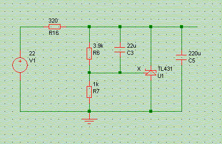
The TL431 is a 3-terminal shunt regulator which some in the DIY community attribute near-magical properties to. And yet, in audio industry it is nearly never used. It is a component with reasonable specs up to 100kHz, and if used in unity-gain mode: meaning that there is direct HF feedback from the voltage rail to the reference input, in the above schematic allowed by capacitor C3. Dare to omit C3 and regulator bandwith and impedance suffer accordingly. Shunts are less easy to apply and almost always impossible to substitute quickly for series regs in commercial gear. In addition, the calculation of dropping resistor R16 can be a nuisance if you don't know the total load current, and note that the 431 is eminently unstable in the absense of output capacitor C5. On the other hand, huge amounts of ripple reduction or isolation can be had when dropper R16 is replaced with an active current source.
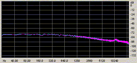
Above is the noise spectrum for the gain-of-five case, i.e. C3 removed, and with a 220uF cap at the output. Noise is slightly lower than the LM317, but perhaps more importantly it is evenly distributed over the whole measurement bandwidth.
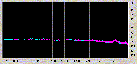
Adding a C3 cap of 22uF then reduces the AC gain to unity, resulting in above noise spectrum. The noise level is now about 12dB lower, which corresponds roughly to the gain difference between both circuits.
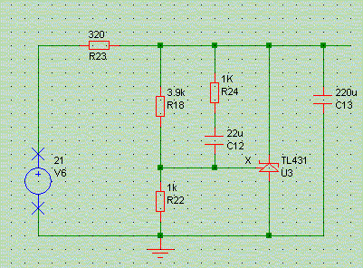
Some people prefer the sound of the TL431 operating in non-unity-gain, i.e. with capacitor C3 removed. As said, this degrades a number of circuit specifications. A reasonable compromise seems to be above circuit, where one resistor added, R24, keeps the circuit at a gain of 2 for HF, and a gain of 5 for DC. No measurements were done, but you can expect noise to be 6dB above the fully-bypassed case.
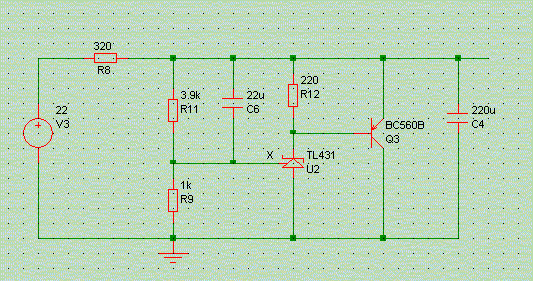
Another interesting variant is the above one, where the 431 is used as a shunt-controlling amplifier driving an emitter follower. Output impedance can be much lower than with a solitary TL431. No noise measurements were done (yet), but I expect them not to be substantially different from the above ones.
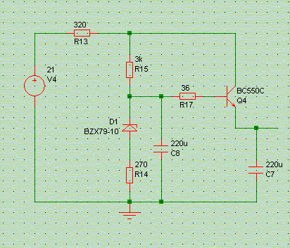
This is about the simplest discrete-device series regulator one could imagine. Ignore R13 (it lowers power dissipation and can be part of an RC input filter for enhanced ripple rejection). The core is zener diode D1, serving as voltage reference. As ordinary zeners are noisy some filtering is required, but zeners have a rather low impedance, hence D1 is put in series with R14: this reduces DC stability, which we can live with, and massively reduces noise. Q4 is the output of the circuit: a bipolar transistor working as emitter follower. At 30mA output current its output impedance is a useable 1 Ohm, and at higher currents it is even lower. Base-stopper R17 is there to ensure stability. That's it.
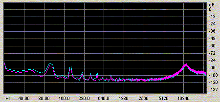
And noise-wise we have a winner here, being 20dB lower than the best of the above circuits! The small peaks in the lower frequencies are at 100Hz and harmonics, clearly related to the mains feed, though it is not quite clear to me how these could have gotten in. Probably a slight routing mistake with a ground wire.
Oh, and listening through the headphones?
Ghostly quiet ...
© Copyright 2004 Werner Ogiers for www.tnt-audio.com